
Process for producing steel sheet and device for continuously annealing steel sheet

A manufacturing method and an annealing device technology, applied in the direction of manufacturing tools, heat treatment process control, coating, etc., can solve the problems of steel plate tensile strength and fatigue strength reduction, strength reduction, large equipment investment, etc., to achieve plating and chemical formation Excellent handling effect

Inactive Publication Date: 2018-08-31
NIPPON STEEL CORP
View PDF13 Cites 0 Cited by
  • Summary
  • Abstract
  • Description
  • Claims
  • Application Information

AI Technical Summary

Problems solved by technology

[0017] In addition, when the atmosphere in the furnace is controlled under the conditions described in Patent Document 4, although the exposure of Si oxides on the surface can be suppressed, since the dew point needs to be set to -10°C or higher, there is a risk of delamination of the steel sheet. Carbon progresses, and the tensile strength and fatigue strength of the steel plate decrease.
In particular, in high-strength steel sheets containing a large amount of C, the reduction in strength due to decarburization becomes a major problem
[0018] In addition, regarding the conditions described in Patent Documents 5 and 6, there is also a problem that it is difficult to guarantee the equations (1) and (3) due to external fluctuations in the amount of moisture in the gas and deterioration of production equipment. P H2O / P H2 Value, dew point and other appropriate conditions
However, in order to set the concentration of hydrogen in the atmosphere gas to 10% or more, special equipment is required, so a large investment in equipment is required for application.

Method used


Image

  • Process for producing steel sheet and device for continuously annealing steel sheet
  • Process for producing steel sheet and device for continuously annealing steel sheet
  • Process for producing steel sheet and device for continuously annealing steel sheet

Examples


Embodiment

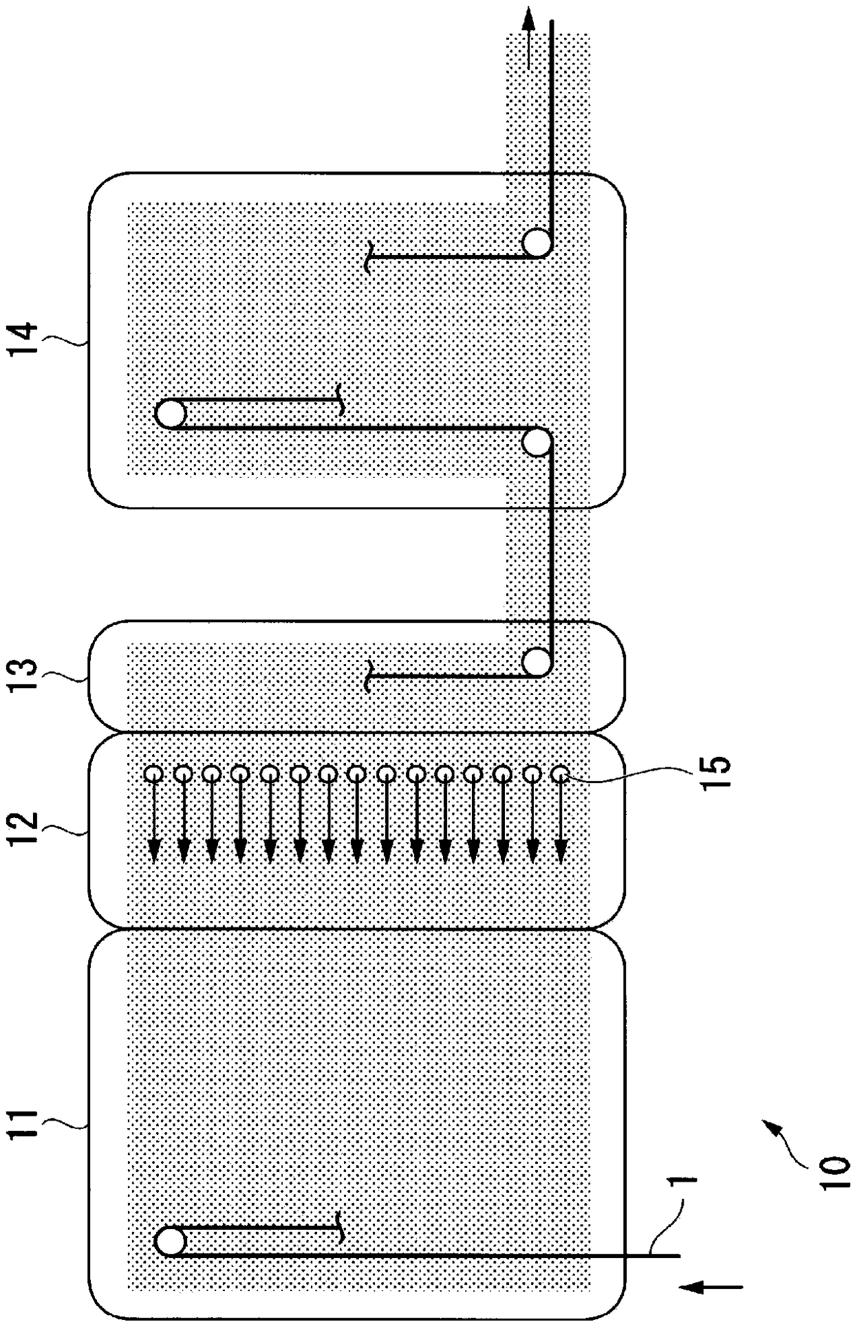
[0123] In order to confirm the effects of the present invention, the results of experiments carried out will be described.

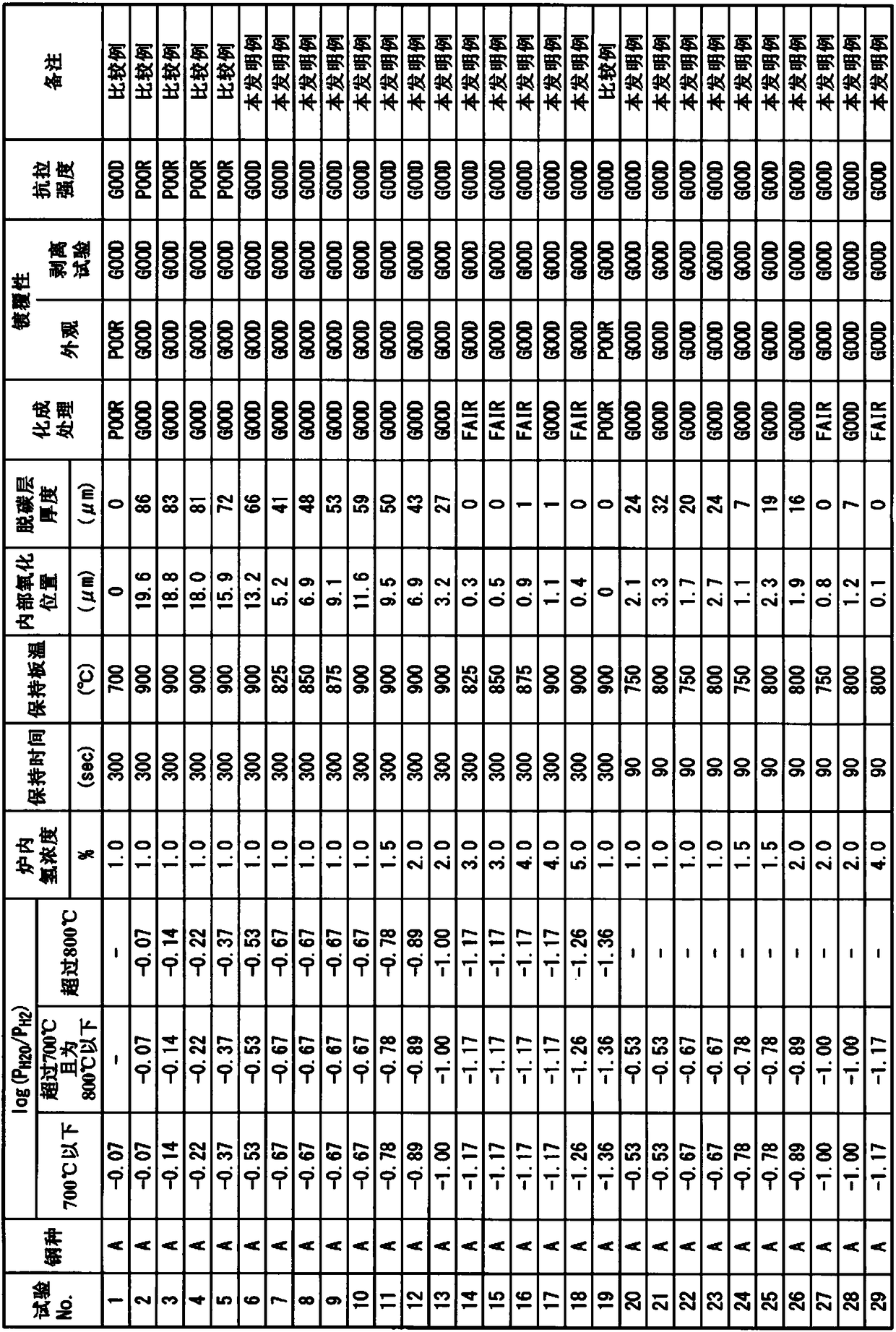
[0124] A cold-rolled steel sheet having a thickness of 1.2 mm produced by a known method was subjected to continuous annealing using the continuous annealing apparatus for steel sheets described in the above-mentioned embodiment. The compositions of the steel sheets used for annealing are as shown in Table 1.

[0125] [Table 1]

[0126]

[0127] In the continuous annealing process, the continuous annealing was carried out under the conditions (holding temperature, holding time) shown in Tables 2 to 8 using a continuous annealing apparatus for steel sheets. The upper limit of the highest heating temperature is set to 900° C. as a value that can be achieved in actual production. In addition, the partial pressure P in the atmosphere in the furnace during heating and holding H2O and hydrogen partial pressure P H2 The resulting relationship log(P H2O ...


PUM


Abstract

This process for producing a steel sheet is a process for producing a high-strength steel sheet having a tensile strength of 780 MPa or higher, and includes a continuous annealing step in which a steel sheet having a given chemical composition is heated to a temperature in the range of 750-900DEG C and the steel sheet is held in the temperature range for 0-300 seconds, thereby conducting continuous annealing. In the continuous annealing step, the atmosphere inside the furnace is regulated so as to have a hydrogen concentration less than 10 vol%, during the period when the heating to a temperature in the range is conducted and during the period when the holding in the temperature range is conducted. When the steel sheet has a temperature of 700DEG C or lower, the furnace-body average valueof log(PH2O / PH2) is greater than -3.01 but less than -0.07. When the steel sheet has a temperature higher than 700oC but not higher than 800oC, the furnace-body average value of log(PH2O / PH2) is greater than -1.36 but less than -0.07. When the steel sheet has a temperature exceeding 800DEG C, the furnace-body average value of log(PH2O / PH2) is greater than -3.01 but not greater than -0.53, and thedew point is lower than -10DEG C.

Description

technical field [0001] The present invention relates to a method for manufacturing a steel plate and a continuous annealing device for a steel plate, in particular to a high-strength steel plate containing 0.050% by mass or more of C, 0.10% by mass or more of Si, and 1.20% by mass or more of Mn, and having a tensile strength of 780 MPa or more. A production method and a continuous annealing apparatus for a steel plate suitable for the production method of the steel plate. Background technique [0002] In recent years, in order to reduce fuel consumption and reduce CO 2 In the automotive field, there is an increasing demand for high-strength steel sheets for bodywork and parts, in order to reduce the weight of the car body and improve the crash safety for the purpose of displacement. Recently, high-strength steel sheets having a tensile strength of 780 MPa or more or 980 MPa or more are being used. [0003] However, if the strength of the steel sheet is increased, material ...

Claims


Application Information

Patent Timeline
IPC IPC(8): C21D9/56C23C2/02C23C2/06C23C22/12C23C22/78
CPCC23C2/06C21D9/56C23C22/12C23C22/78C23C2/40C21D6/002C21D9/46C21D11/00C22C38/001C22C38/002C22C38/02C22C38/04C22C38/06C22C38/08C22C38/12C22C38/14C22C38/16C22C38/18C23C2/0222C23C2/0038C23C2/02C22C38/42C22C38/48C22C38/50C21D9/561C23C2/0224
Inventor 北泽贵幸植田浩平川田裕之平松薰
Owner NIPPON STEEL CORP
Learn More