Engine device

An engine and auxiliary machine technology, applied in the direction of engine components, machines/engines, lubricant conduit devices, etc., can solve the problem of low ratio of rigidity increase, and achieve the effect of increasing surface area, preventing deformation, and preventing poor rotation of camshafts

Pending Publication Date: 2018-11-23
YANMAR POWER TECHNOLOGY CO LTD
View PDF7 Cites 2 Cited by
  • Summary
  • Abstract
  • Description
  • Claims
  • Application Information

AI Technical Summary

Problems solved by technology

However, even if the wall thickness of the cylinder is increased, there is still a problem that the ratio of the increase in rigidity to the increase in weight will appear to be low

Method used


Image

  • Engine device
  • Engine device
  • Engine device

Examples


Embodiment Construction

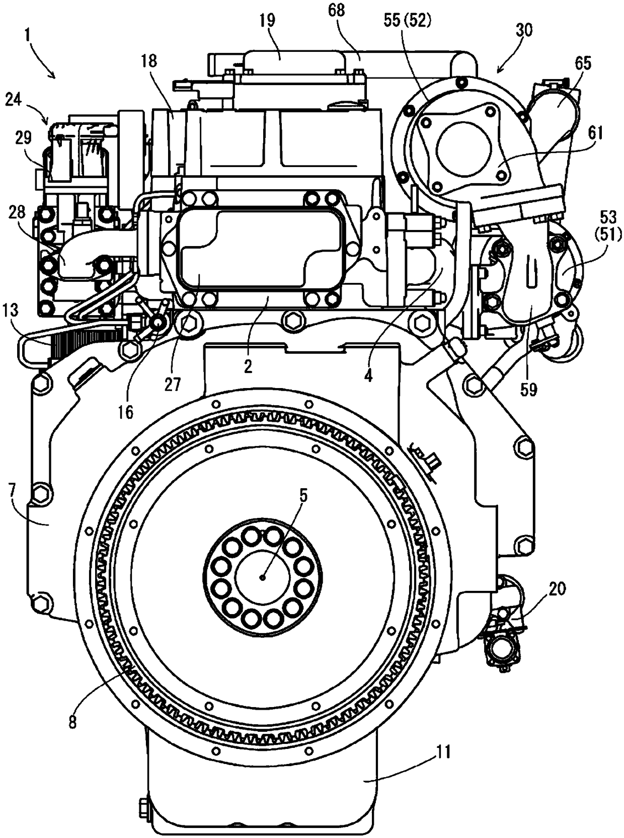
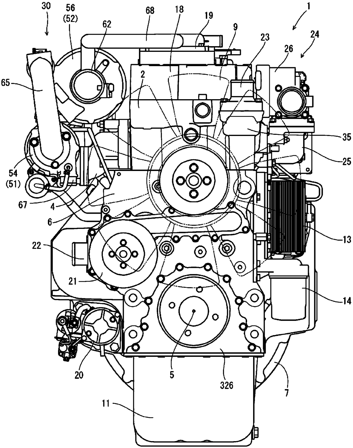
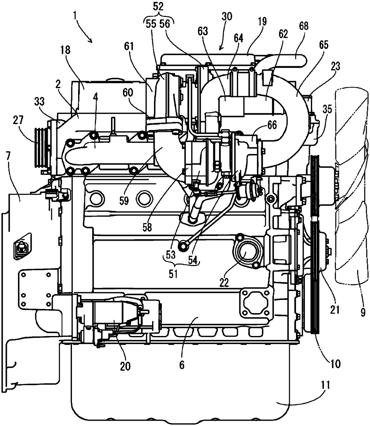
[0044] Hereinafter, specific embodiments of the present invention will be described based on the drawings. First, refer to Figure 1 to Figure 8 The overall structure of the diesel engine (engine unit) 1 will be described. In addition, in the following description, the two sides parallel to the crankshaft 5 (sides sandwiching the crankshaft 5) are called left and right, the side where the flywheel cover 7 is installed is called the front side, and the side where the cooling fan 9 is installed is called the front side. For the rear side, they are used as references for the four directions and the up and down positional relationship of the diesel engine 1 for the sake of explanation.

[0045] like Figure 1 to Figure 8 As shown, an intake manifold 3 is arranged on one side of the diesel engine 1 parallel to the crankshaft 5 , and an exhaust manifold 4 is arranged on the other side. In the embodiment, the intake manifold 3 is formed integrally with the cylinder head 2 on the r...


PUM


Abstract

An engine device equipped with a cylinder block 6 rotatably supporting a crankshaft. At one end, in the shaft center direction of the crankshaft, of the two side parts 301 and 302 of the cylinder block 6 running in the shaft center direction of the crankshaft, a protruding part 305 extending in the direction away from the crankshaft, and reinforcing ribs 306, 307, 308, 309, 310, and 311, which areprovided between the respective side walls of the two side parts 301 and 302 and the protruding parts 304 and 305 so as to expand toward the protruding part 305 side, are integrally formed on the cylinder block 6.

Description

technical field [0001] The present invention relates to an engine device, and more particularly, to an engine device including a cylinder block that rotatably supports a crankshaft. Background technique [0002] An engine device including a cylinder block rotatably supporting a crankshaft is known (for example, refer to Patent Document 1). The cylinder block is one of the media that transmits explosive force to the crankshaft system, and is also one of the most important strength elements that must support the inertial load and the like of the crankshaft system. In addition, the construction of the cylinder block can also greatly affect the size, weight, overall durability, noise, etc. of the engine. [0003] patent documents [0004] Patent Document 1: Japanese Patent Laid-Open No. 2012-189027 Contents of the invention [0005] In the past, as a method of increasing the rigidity of the cylinder body, the method of making the wall thickness of the cylinder body thicker ...

Claims


Application Information

Patent Timeline
Patent Type & Authority Applications(China)
IPC IPC(8): F02F7/00F02F1/00
CPCF02F1/00F02F7/00F02F7/0068F02F7/0073F02F1/004F02F1/20F02F7/0021F01M11/02F02F7/0043F02F7/0082
Inventor 上里晃一长绳宏明
Owner YANMAR POWER TECHNOLOGY CO LTD
Why Eureka
Try Eureka