Eureka AIR delivers breakthrough ideas for toughest innovation challenges, trusted by R&D personnel around the world.

Joint for concentration solar plants

A joint and elastic device technology, applied in the field of joints, can solve the problems of increased volume and damaged pipe structure, etc.

Active Publication Date: 2018-11-23
密凯加机械技术股份公司
View PDF9 Cites 0 Cited by
  • Summary
  • Abstract
  • Description
  • Claims
  • Application Information

AI Technical Summary

Problems solved by technology

On the one hand, the use of these substances allows to increase the energy efficiency of the device, but on the other hand, it brings about additional technical requirements, such as the need to prevent the solidification of the heat transfer fluid, which in addition to the formation of inclusions in the tubes In addition to the solid residue, the structure of the tube may be damaged during the melting step of the solid residue due to the simultaneous increase in volume from the solid to the liquid phase

Method used


Image

  • Joint for concentration solar plants
  • Joint for concentration solar plants
  • Joint for concentration solar plants

Examples


Embodiment Construction

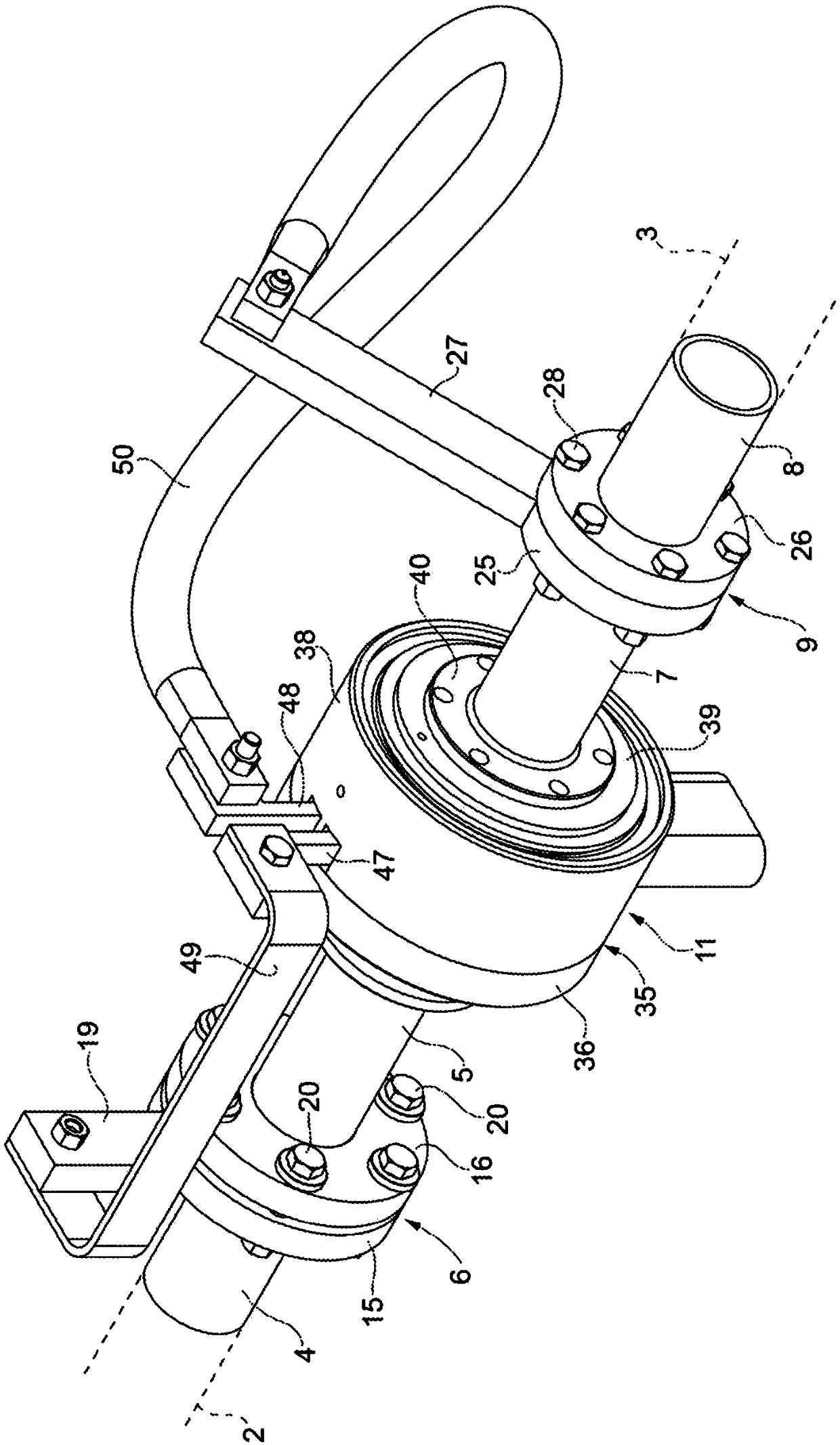
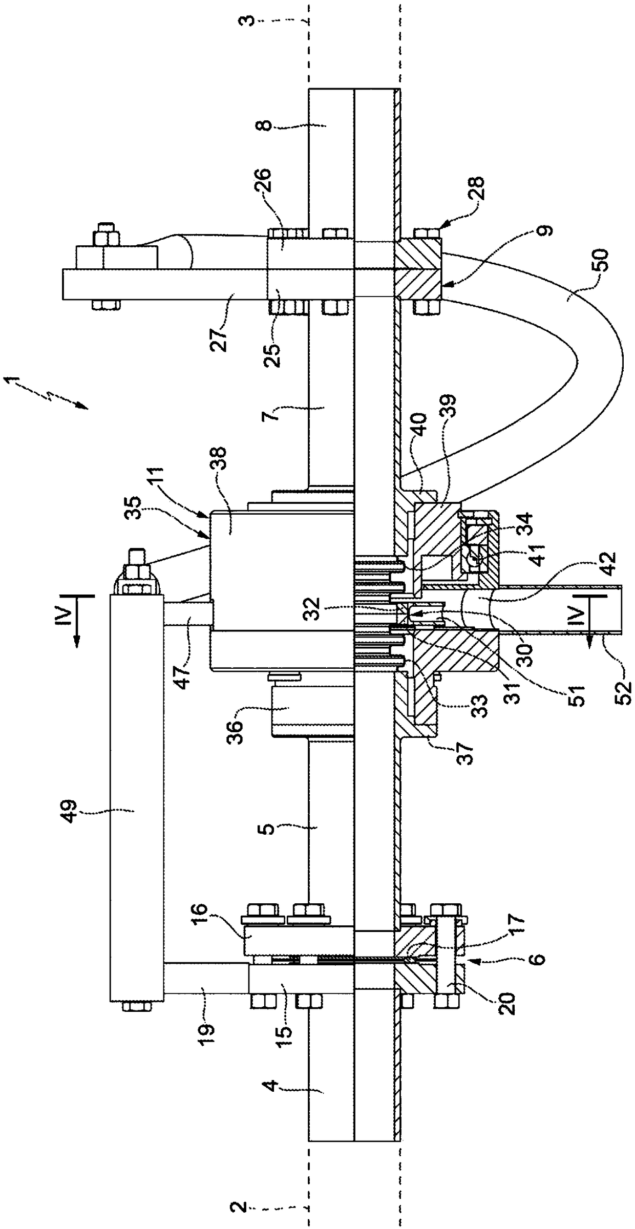
[0021] refer to figure 1 and figure 2 , reference numeral 1 as a whole designates a connecting unit for sealingly connecting two coaxial, mutually rotating tubes 2 , 3 (partially shown). In particular, pipe 2 may be formed by a fixed ground pipe; pipe 3 may be formed by a connecting pipe connected to a receiving pipe of a parabolic mirror of a CSP system (not shown) using a heat transfer fluid with a relatively high freezing temperature , such as NaNO 3 +KNO3. Tube 3 is preferably a flexible tube.

[0022] The connection unit basically consists of:

[0023] a first end tube 4 rigidly and sealingly connected to the tube 2;

[0024] first intermediate pipe 5;

[0025] an insulating joint 6 connecting the first end tube 4 to the first intermediate tube 5 and interposed axially between the first end tube 4 and the first intermediate tube 5;

[0026] the second tube 7; and

[0027] A swivel joint 11 sealingly connects the first intermediate tube 5 to the second tube 7 .

...


PUM


Abstract

A connection unit for sealingly connecting two pipes (2, 3) traversed by an electric current and mutually rotatable. The connection unit includes a first end element (4) to be connected to one of thepipes (2), a first intermediate pipe (5), an insulating joint (6) interposed between the first end element (4) and the first intermediate pipe (5), a second pipe (7) to be connected to another pipe (3), a rotary joint (11) sealingly connecting with a possible relative rotation the first intermediate pipe (5) to the second pipe (7, 8), a bypass circuit (19, 49, 42, 50, 27) electrically connecting the first end element (4) to the second pipe (7, 8), and a heating element (42) in series with the bypass circuit and arranged in the rotary joint (11).

Description

technical field [0001] The invention relates to joints for concentrating solar energy devices. Background technique [0002] A Concentrating Solar Plant (CSP) comprises a plurality of parabolic mirrors (parabolic troughs) to concentrate solar energy on respective receiving tubes arranged in the focal points of the mirrors through which a heat transfer fluid flows. [0003] The high temperature achieved by the heat transfer fluid allows the accumulated heat to be used to generate supersaturated steam which is passed through the heat exchanger, for example, to spin a turbine and generate electricity. [0004] To increase the efficiency of the device, the mirrors are configured to rotate following the apparent motion of the sun. Thus, during the day, the receiving tube rotates integrally with the parabolic mirror and is interconnected by means of a fixed ground tube. [0005] Therefore, it is necessary to provide a fluid-tight joint provided between the rotating tube and the ...

Claims


Application Information

Patent Timeline
Patent Type & Authority Applications(China)
IPC IPC(8): F16L25/01F16L27/08F24S70/00F24S30/40F16L53/00F16L53/38
CPCF16L25/01F16L27/082F16L27/0828F16L53/38F24S80/30F24S30/425Y02E10/47
Inventor 保罗·皮亚琴蒂法布里齐奥·拉尼马西米利亚诺·博尔阿索
Owner 密凯加机械技术股份公司
Why Eureka
Eureka Blog
Learn More