Continuous flowing preparation system and method

A preparation system and controller technology, applied in the fields of materials, chemical industry, and chemistry, can solve the problems of limited heat transfer rate, unsuitable for large flow continuous flow preparation, etc., to improve heat transfer efficiency, rapid heating, and increase heat transfer rate Effect

Inactive Publication Date: 2018-11-27
苏州欣影生物医药技术有限公司
View PDF5 Cites 6 Cited by
  • Summary
  • Abstract
  • Description
  • Claims
  • Application Information

AI Technical Summary

Problems solved by technology

[0005] The purpose of the present invention is to propose a continuous flow preparation system and method, which overcomes the defects of the current flow chemical synthesis system that the heat transfer rate is limited and is not suitable for large-flow continuous flow preparation, improves the heat transfer efficiency of the reactor, and improves the efficiency of flow synthesis. production efficiency, and can realize the adjustment of multi-parameters in the reaction process

Method used


Image

  • Continuous flowing preparation system and method
  • Continuous flowing preparation system and method
  • Continuous flowing preparation system and method

Examples


Embodiment 1

[0047] Embodiment 1-continuous flow preparation system

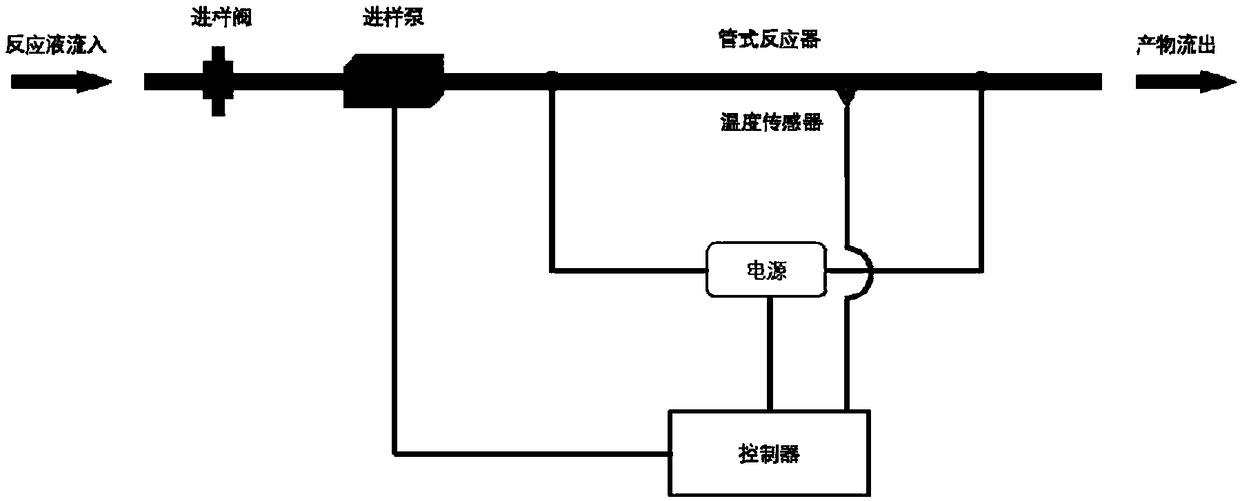
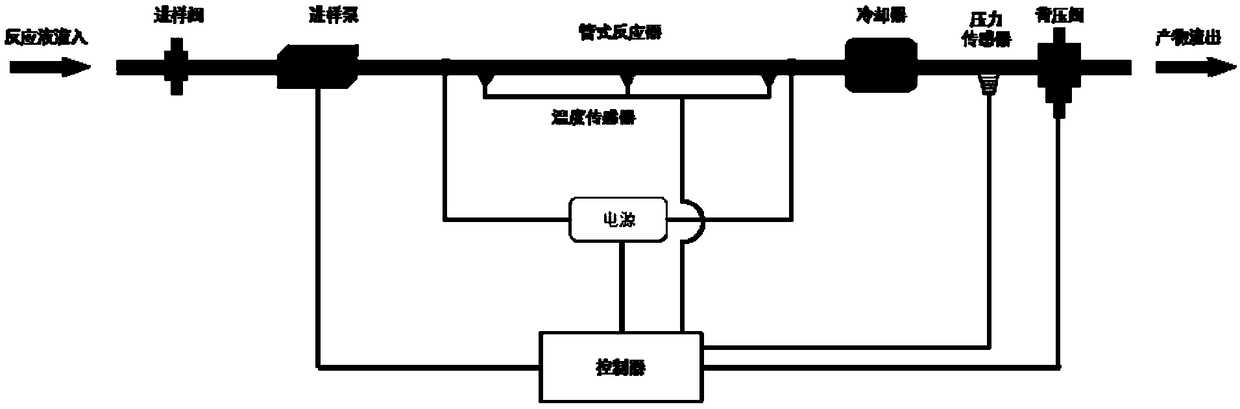
[0048] refer to Figure 1 to Figure 3 As shown, the continuous flow preparation system of the present invention includes a controller and sequentially connected sampling channels, reactors and sampling channels; the reaction solution flows into the tubular reactor from the sampling channel, and then flows out of the product from the sampling channel;

[0049] refer to Figure 4 to Figure 12 , the reactor of the present invention is a tubular reactor, including a conductive reaction tube and a power module; the power module includes a power output terminal and a control terminal, and the power output terminal is electrically connected to the two ends of the reaction tube; the reaction tube is provided with a temperature Sensor, the temperature sensor detects the temperature signal in the reactor and transmits it to the controller. The controller controls the output voltage of the power module through the control terminal...

Embodiment 1-1

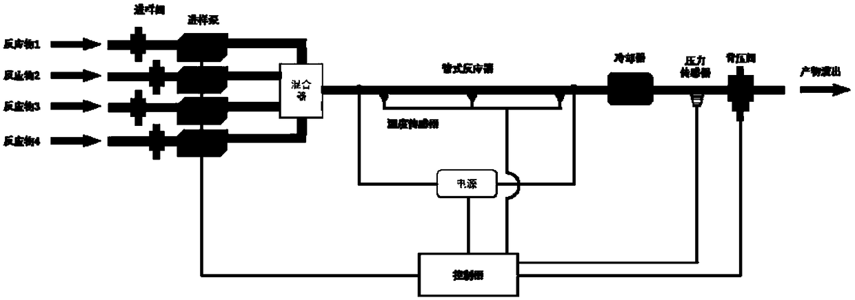
[0052] Based on Example 1, refer to Figure 1 to Figure 3 , There are one or more sampling channels, the sampling channel is provided with a sampling valve and a sampling pump, the controller controls the opening or closing of the sampling valve, and the start, pump speed and shutdown of the sampling pump. The sampling valve and the sampling pump can adopt existing metering valves and metering pumps. The controller can be realized by using existing computer, industrial computer or microcontroller. By controlling the flow rate of each sampling pump, the flow and ratio of different reactants can be flexibly adjusted.

[0053] Such as image 3 , when there are multiple sampling channels, the sampling outlets of the multiple sampling channels are connected to the sampling ports of the tubular reactor through the mixer. The mixer is used to mix the reactants pumped in from multiple sampling channels, and then enter the tubular reactor, and the mixer can adopt the existing T-type...

Embodiment 1-2

[0064] The difference between this embodiment and embodiment 1-1 is:

[0065] refer to Figure 5 , Figure 8 , Figure 9 with Figure 11 As shown, the reaction tube of the tubular reactor is a serpentine tube (S-shaped tube). Under the same length of the reaction tube, the floor area of ​​the reactor can be effectively reduced compared with the linear tubular reactor.


PUM


Abstract

The invention discloses a continuous flowing preparation system and method. The system comprises a controller, and a sample feeding channel, a reactor and a sample discharging channel successively connected. A reaction liquid enters a tubular reactor through the sample feeding channel and a product flows out from the sample discharging channel; the reactor is the tubular reactor which comprises aconductive reaction tube and a power supply module. The power supply module comprises a power supply output end and a control end. The output end of the power supply is electrically connected to two ends of the reaction tube; a temperature sensor is arranged on the reaction tube, the temperature sensor detects a temperature signal in the reactor and transmits the temperature signal to the controller, and the controller controls the output voltage of the power supply module through the control end of the power supply module according to the received temperature signal so as to control the reaction temperature in the reactor. The system and method can overcome the defects that an existing flowing chemical synthetic system is limited in heat transfer rate and is not suitable for large flow continuous flowing preparation, improves the heat transfer efficiency of the reactor and the production efficiency of flowing synthesis, and multiple parameters in the reaction process can be adjusted.

Description

technical field [0001] The invention relates to the technical fields of chemistry, material and chemical industry, especially the continuous flow preparation system and method. Background technique [0002] Flow Chemistry, or Continuous Flow Chemistry, refers to a chemical reaction in which materials are transported by a pump and carried out in a specific channel in a continuous flow mode to achieve continuous flow synthesis. While flow chemistry is a well-established technology in the production of bulk chemicals such as those in the petrochemical industry, it is a relatively new concept that is still in the laboratory stage of development in the synthesis of complex chemicals such as pharmaceuticals. Due to its unique advantages in complex chemical reactions, especially in the preparation of pharmaceutical intermediates, flow synthesis has been favored by international pharmaceutical giants. Large companies such as Merck AG and Sigma-Aldrich began related research at the e...

Claims


Application Information

Patent Timeline
Patent Type & Authority Applications(China)
IPC IPC(8): B01J19/24B01J19/00
CPCB01J19/0013B01J19/2415B01J2219/00058B01J2219/00135B01J2219/00162
Inventor 赵恩宇曾剑峰
Owner 苏州欣影生物医药技术有限公司
Why Eureka
Try Eureka