Drilling machining device for synchronously removing cutting scraps

A technology of machining and drilling equipment, used in metal processing equipment, metal processing mechanical parts, manufacturing tools, etc., can solve the problems of drill bit damage, chip heating melting, chip processing, etc., to alleviate vibration, facilitate tool setting, and strengthen The effect of the drill

Inactive Publication Date: 2018-11-27
黄萧剑
View PDF0 Cites 14 Cited by
  • Summary
  • Abstract
  • Description
  • Claims
  • Application Information

AI Technical Summary

Problems solved by technology

[0004] The object of the present invention is to provide a drilling equipment for synchronous removal of cutting waste for mechanical processing, to solve the existing drilling equipment proposed in the above-mentioned background technology. During actual drilling, the cleaning effect for cutting chips is poor, When drilling, the chips are wrapped around the outside of the drill bit, resulting in the accumulation of heat outside the drill bit, which is easy to cause the chips to be heated and melted, which will not only damage the drill bit, but also affect the drilling quality. The treatment of chips is still at a low level. The conventional method is to The chips are blown away, but the chips cannot be collected and processed, resulting in low chip removal efficiency and poor effect

Method used


Image

  • Drilling machining device for synchronously removing cutting scraps
  • Drilling machining device for synchronously removing cutting scraps
  • Drilling machining device for synchronously removing cutting scraps

Examples


Embodiment Construction

[0028] The following will clearly and completely describe the technical solutions in the embodiments of the present invention with reference to the accompanying drawings in the embodiments of the present invention. Obviously, the described embodiments are only some, not all, embodiments of the present invention. Based on the embodiments of the present invention, all other embodiments obtained by persons of ordinary skill in the art without making creative efforts belong to the protection scope of the present invention.

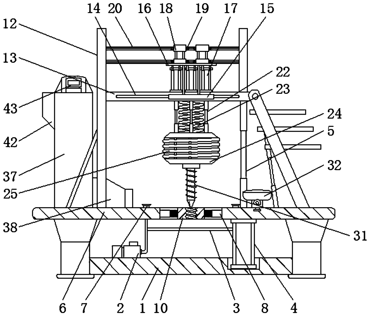
[0029] see Figure 1-7, the present invention provides a technical solution: a drilling device for synchronous removal of cutting waste for mechanical processing, including a base 1 and a tool holder 24, an air pump 2 is installed on the upper left side of the base 1, and the right side of the air pump 2 is connected to There is an air pipe 3, a first hydraulic cylinder 4 is arranged on the upper right side of the base 1, and a first hydraulic rod 5 is install...


PUM


Abstract

The invention discloses a drilling machining device for synchronously removing cutting scraps. The drilling machining device comprises a base and a tool rest, wherein an air pump is installed on the left side of the upper portion of the base, the right side of the air pump is communicated with an air pipe, the right side of the upper portion of the base is provided with a first hydraulic cylinder,a first hydraulic rod is installed above the first hydraulic cylinder, a basic table is arranged above the air pump, a supporting rod is fixed to the left side of the upper portion of the basic table, a horizontal supporting rod frame is installed on the right side of the upper portion of the supporting rod, the middle of the horizontal supporting rod frame is provided with a lifting plate, a damping spring is installed below the lifting plate, and the tool rest is arranged below the damping spring. The drilling machining device for synchronously removing cutting scraps makes the basic tablehave an air suction fixing structure serving as a clamp by arranging a suction cup and the air pump, utilizes the air suction fixing mode to fix a workpiece, is convenient and quick and can limit a drilling route and range under the effect of a pressing-fixing ring.

Description

technical field [0001] The invention relates to the technical field of drilling equipment, in particular to a drilling equipment for synchronous removal of cutting waste for mechanical processing. Background technique [0002] Drilling machine refers to the general name of machinery and equipment that leaves cylindrical holes or holes on the target by means of rotary cutting or rotary extrusion with a tool that is harder and sharper than the target. Machines, drilling machines, through-hole machines, etc., achieve the desired effect by drilling precision parts. Drilling machines include semi-automatic drilling machines and fully automatic drilling machines. With the increase in human resource costs, most enterprises Fully automatic drilling machines are considered as the development direction. Drilling machines play a very important role in mechanical processing and are very common processing equipment. [0003] However, the existing drilling equipment has a poor cleaning e...

Claims


Application Information

Patent Timeline
Patent Type & Authority Applications(China)
IPC IPC(8): B23Q3/08B23Q11/00B23Q5/26B23Q11/12B23Q11/10
CPCB23Q3/08B23Q3/088B23Q5/26B23Q11/0032B23Q11/0042B23Q11/10B23Q11/12
Inventor 黄萧剑
Owner 黄萧剑
Why Eureka
Try Eureka