Plastic rubbish crushing device
A crushing device and plastic waste technology, which is applied in plastic recycling, mechanical material recycling, recycling technology, etc., can solve problems such as inability to achieve uniform feeding, crushing rollers are easy to be stuck, and affect work efficiency, so as to prevent card owners , Guarantee work efficiency, improve the effect of contact effect
- Summary
- Abstract
- Description
- Claims
- Application Information
AI Technical Summary
Problems solved by technology
Method used
Image
Examples
Embodiment 1
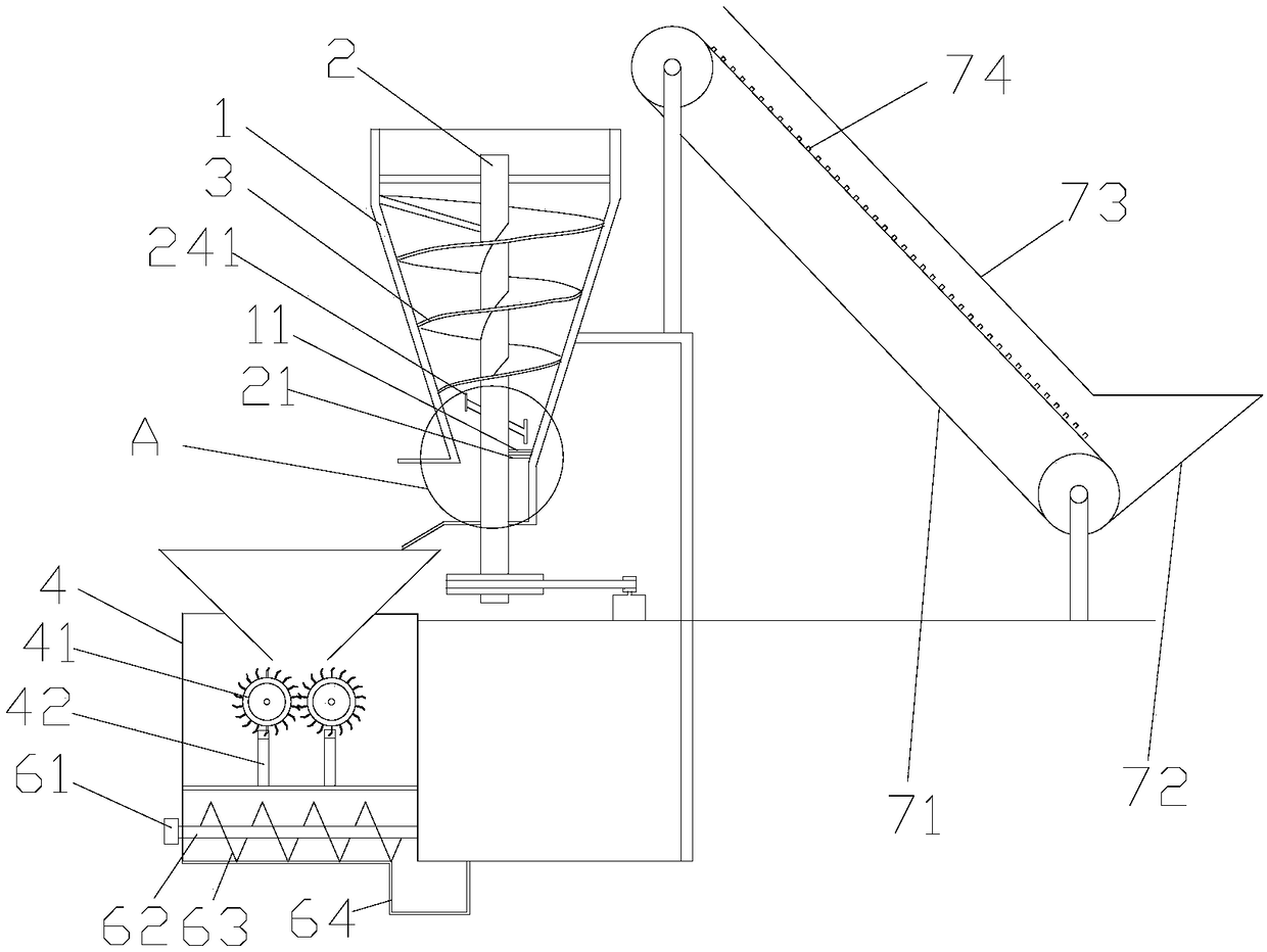
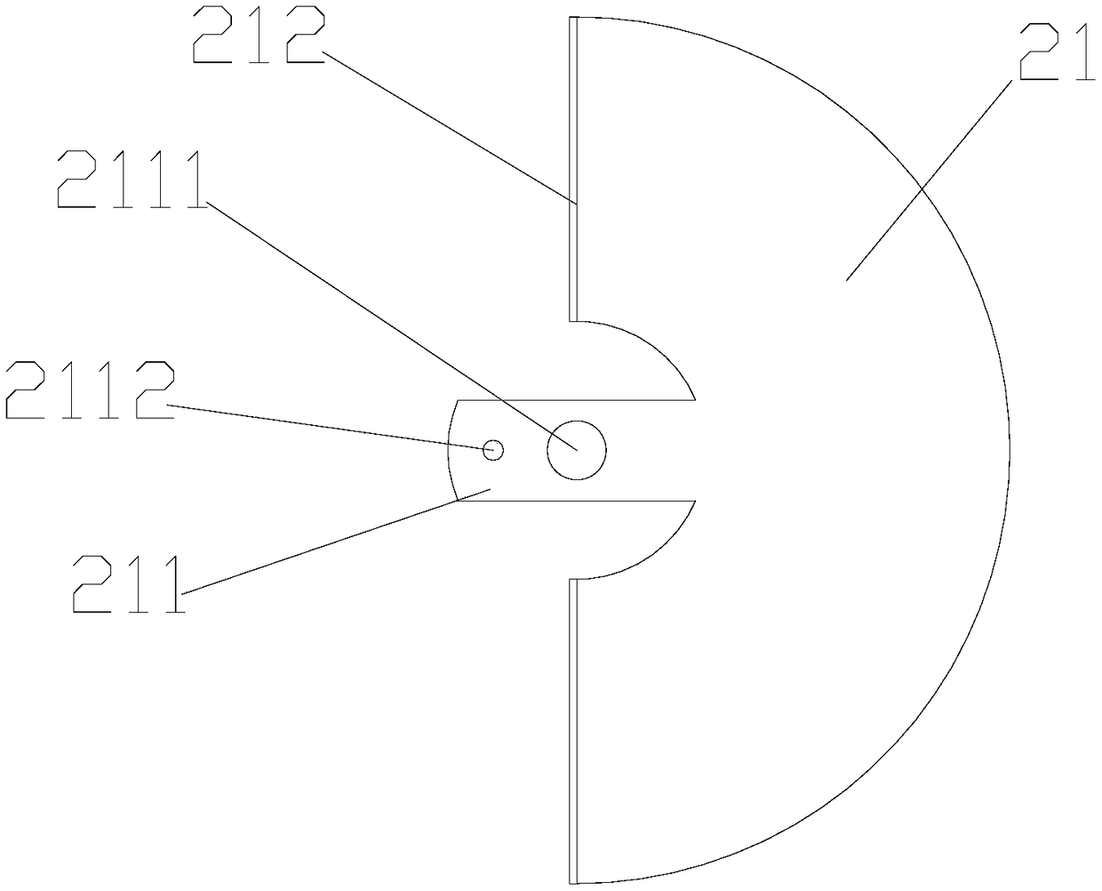
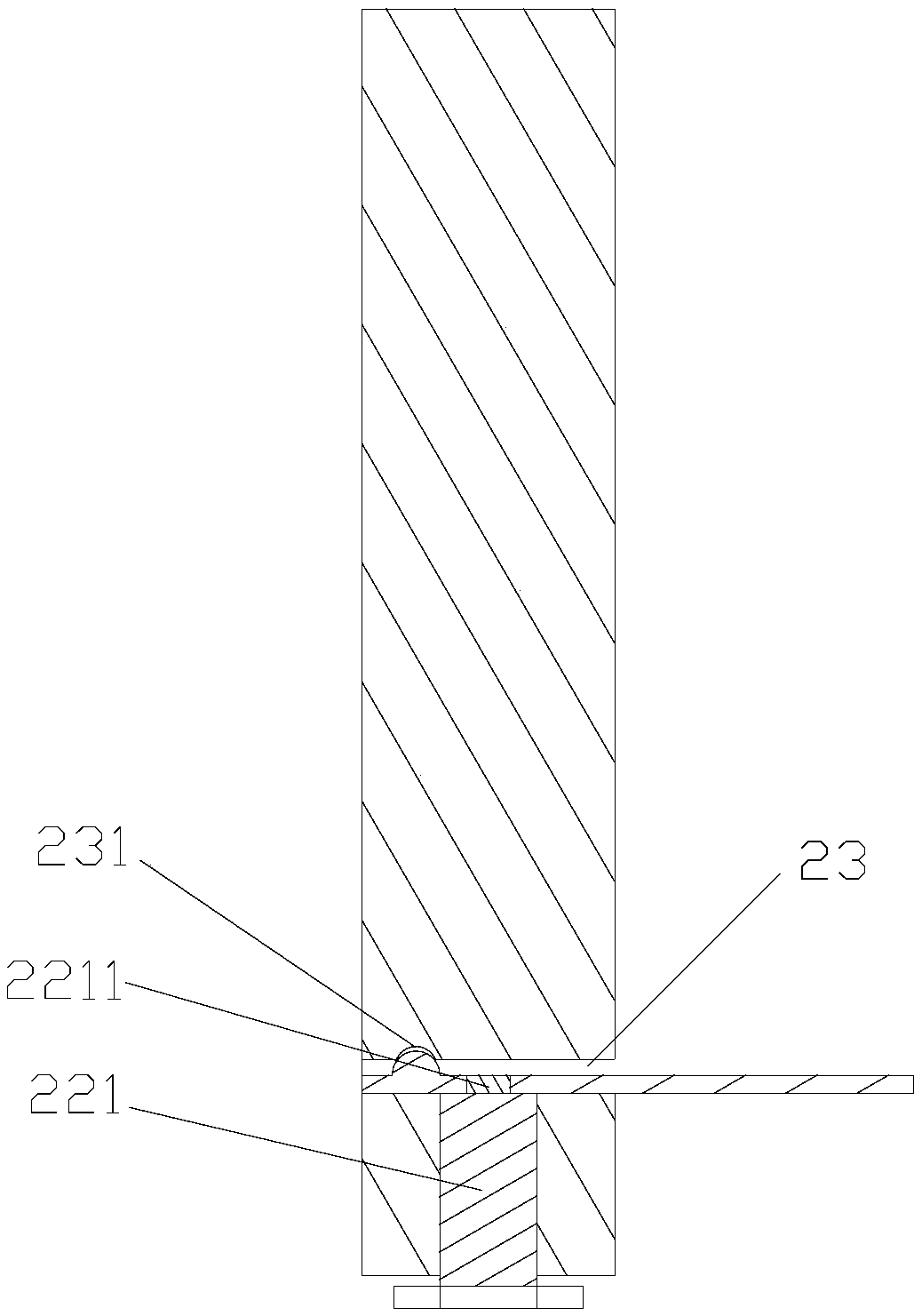
[0027] Such as Figure 1-5 As shown, a plastic waste crushing device includes a feeding mechanism, a feeding mechanism, a crushing mechanism, and a discharging mechanism. The feeding mechanism includes a conveyor belt 71, an upper hopper 72 and a protective cover 73. The conveyor belt 71 is set obliquely and , the conveyor belt 71 is a conventional conveyor belt, and the surface of the conveyor belt 71 is bonded with an anti-skid bar 74 made of plastics, and the anti-skid bar 74 is set to increase the friction between the plastic waste and the conveyor belt parts, which is convenient for transportation; the protective cover 73 It is a metal cover made of a thin metal skin, and the protective cover 73 is fixedly installed above the conveyor belt 71 to prevent plastic waste from falling randomly during the feeding process; the upper hopper 72 is located at the bottom of the conveyor belt, and the upper hopper 72 is a The metal hopper, the bottom of the upper hopper 72 communicat...
Embodiment 2
[0033] Such as Figure 6-8 As shown, the difference between this embodiment and Embodiment 1 is that this embodiment also discloses that a shock absorbing mechanism is provided at the bottom of the crushing box 4. Specifically, the shock absorbing mechanism includes a base 80, a guide column 81 and a spring 82, Described base 80 is a metal seat, and described guide column 81 is metal column; Described base 80 is provided with the through hole 84 that guide column 81 passes through, and through hole 84 not only can be used for guide column 81 to move up and down, but also to guide column 81. The post 81 plays a position-limiting role, preventing the device from shaking left and right when it is working; the inner wall of the through hole 84 is provided with a spiral groove 83, and the bottom of the crushing box 4 is provided with the same spiral groove, and the spring 82 is available on the market. One end of the spring 82 is screwed into the spiral groove on the base 80, and t...
Embodiment 3
[0035] Such as Figure 9-10 As shown, the difference between this embodiment and Embodiment 1 is that this embodiment discloses that a cleaning mechanism is provided under the crushing box. Specifically, the cleaning mechanism includes a cleaning box 9, a stirring assembly arranged in the cleaning box, a driving The driving part 91, the water tank 92 and the connecting pipe 93 that the stirring assembly rotates, one side of the cleaning tank is provided with a discharge port 900, and the other side is provided with a drain port 901, and the driving part is selected from a commercially available conventional motor. The water tank 92 is arranged above the cleaning tank 9 for water supply, the connecting pipe 93 is an L-shaped metal pipe, one end of the connecting pipe 93 communicates with the water tank 92, and the other end communicates with the cleaning tank 9; the stirring assembly includes an output shaft 94 , the fixed sleeve 95, the first stirring rod 96 and the second sti...
PUM
 Abstract
Description
Claims
Application Information
 - R&D
- Intellectual Property
- Life Sciences
- Materials
- Tech Scout
- Unparalleled Data Quality
- Higher Quality Content
- 60% Fewer Hallucinations
Browse by: Latest US Patents, China's latest patents, Technical Efficacy Thesaurus, Application Domain, Technology Topic, Popular Technical Reports.
© 2025 PatSnap. All rights reserved.Legal|Privacy policy|Modern Slavery Act Transparency Statement|Sitemap|About US| Contact US: help@patsnap.com


