Clamping device for high-temperature tensile sample for metal sheet and use method of clamping device
A technology for clamping devices and tensile samples, applied to measuring devices, using stable tension/pressure to test material strength, instruments, etc., can solve problems such as complex structure, cumbersome operation, and affecting test efficiency, and achieve device structure Small size, good coaxiality, and easy-to-use effects
- Summary
- Abstract
- Description
- Claims
- Application Information
AI Technical Summary
Problems solved by technology
Method used
Image

Examples
Embodiment 1
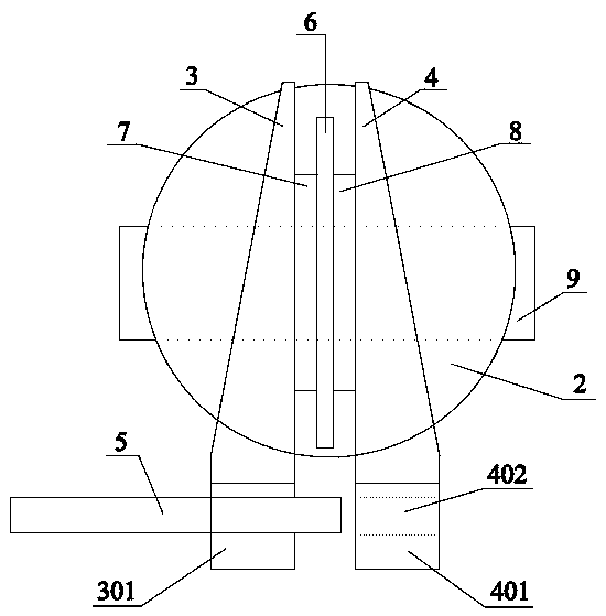
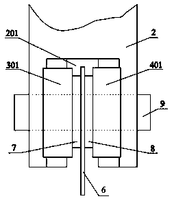
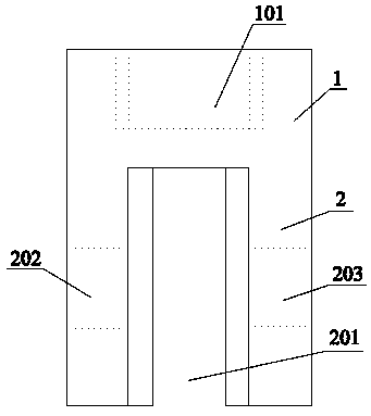
[0041] As shown in the accompanying drawings, a clamping device for a high-temperature tensile sample of a metal sheet, the two ends of the sample 6 are provided with fixing parts, and each fixing part is provided with a pin hole, and the clamping device passes through The pin hole clamps and fixes the sample 6. The clamping device includes a clamp body 1 and a clamping part 2 connected to the clamp body 1. One end of the clamp body 1 is provided with a threaded hole 101, and the threaded hole A connecting rod is installed in 101, and one end of the connecting rod away from the threaded hole 101 is connected to the tensile test equipment, and the other end of the clamp body 1 is provided with a clamping part 2 integrally arranged with the clamp body, so The end of the clamping part 2 away from the threaded hole 101 is provided with a groove 201 with an isosceles trapezoidal cross section, and the groove 201 extends along the end of the clamping part 2 to one side of the clamp b...
Embodiment 2
[0059] According to the clamping device and its use method in Example 1, the material of the thin metal plate is selected as Ti70, the thickness of the thin metal plate is δ=1.5mm, and the test temperature of the high-temperature furnace is 600°C. A high-temperature tensile test is carried out, and the obtained Stress-strain curve see Figure 7 .
Embodiment 3
[0061] According to the clamping device and the method of use thereof in Example 1, the material of the thin metal plate is selected as Ti31, the thickness of the thin metal plate is δ=0.7mm, and the test temperature of the high-temperature furnace is 350°C. A high-temperature tensile test is carried out, and the obtained Stress-strain curve see Figure 8 .
[0062] It can be seen from Example 2 and Example 3 that using the clamping device of the present invention and its method of use to carry out high-temperature tensile tests, the use of wedge-shaped gaskets I3 and wedge-shaped gaskets II4 can complete the high-temperature testing of metal sheets of multiple specifications. Tensile test, after the end of the test, no obvious deformation was seen at the fixed end of the sample, and the linearity of the elastic segment in the obtained stress-strain curve was good, indicating that the universality and usability of the clamping device and its method of use of the present invent...
PUM
 Abstract
Description
Claims
Application Information
 - R&D
- Intellectual Property
- Life Sciences
- Materials
- Tech Scout
- Unparalleled Data Quality
- Higher Quality Content
- 60% Fewer Hallucinations
Browse by: Latest US Patents, China's latest patents, Technical Efficacy Thesaurus, Application Domain, Technology Topic, Popular Technical Reports.
© 2025 PatSnap. All rights reserved.Legal|Privacy policy|Modern Slavery Act Transparency Statement|Sitemap|About US| Contact US: help@patsnap.com