Backlight module and display device

A backlight module, light source technology, applied in the direction of light guide, optics, optical components, etc., can solve problems such as the inability to achieve four-sided narrow borders

Inactive Publication Date: 2018-11-27
BOE TECH GRP CO LTD +1
View PDF6 Cites 5 Cited by
  • Summary
  • Abstract
  • Description
  • Claims
  • Application Information

AI Technical Summary

Problems solved by technology

[0005] The purpose of the present invention is to overcome the disadvantages of the above-mentioned prior art that the four-sided narrow frame can...

Method used


Image

  • Backlight module and display device
  • Backlight module and display device
  • Backlight module and display device

Examples


Embodiment approach 1

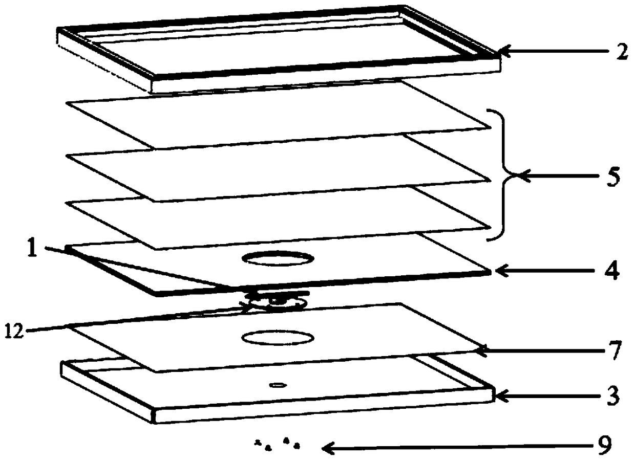
[0050] refer to Figure 4 The three-dimensional structure schematic diagram of the light source assembly is shown, the light source assembly may include a drive motor 8 with a drive shaft and a light emitting part 1 .

[0051] In this example implementation, refer to Figure 5 As shown in the structural schematic diagram of the light emitting part 1, the light emitting part may include a PCB board 15, which is arranged in a strip shape, and the two sides of the PCB board 15 are symmetrically fixed to the drive shaft of the drive motor 8, so that the drive motor 8 can drive the PCB board 15 Rotate to form a circular surface; the side of the PCB board 15 close to the diffusion assembly 5 is provided with a COB light source 13, that is, the entire upper surface of the PCB board 15 is provided with a COB light source 13; the two ends of the length direction of the PCB board 15 are close to the hole wall One side is provided with an LED light source 14 .

[0052] COB light source...

Embodiment approach 2

[0065] The main difference between this exemplary embodiment and the first exemplary embodiment is that: the light source assembly is different, and this exemplary embodiment directly adopts a surface light source; at the same time, there is no need to set a second through hole on the back plate 3, and it is not necessary to set a second through hole on the reflective plate. A through hole. The differences will be described in detail below.

[0066] In this exemplary embodiment, the holes on the light guide plate 4 may be blind holes, and the shape of the blind holes may be set as a rectangle. The blind hole is set at the center of the light guide plate 4 . Of course, those skilled in the art can understand that the holes on the light guide plate 4 can also be through holes, and in this case, the light emitting part 1 can be fixed on the reflective plate. The shape of the hole can also be circular, trapezoidal or elliptical or the like. The blind hole may not be arranged at...


PUM


Abstract

The invention relates to the technical field of display, and provides a backlight module. The backlight module comprises a light guide plate, a diffusion assembly and a light source assembly. A lightguide plate is provide with a hole; The diffusion assembly is arranged on the light guide plate; A light source assembly include a light emitting portion dispose in that hole, the light emitting portion including a COB light source having a light emitting surface toward the diffusion assembly and an LED light source have a light emitting surface toward the hole wall; The transmittance of the diffuser relative to the COB light source is smaller than the transmittance of the rest of the diffuser. The light emitting part is arranged in the hole of the light guide plate, and the backlight module does not exist on the light entrance side, and the periphery of the backlight module can be arranged as a narrow frame. The light uniformity of the whole backlight module can be adjusted by the different transmittance of the diffusion module. The COB light source emits uniformly and has no light spots, which further improves the uniformity of the light emitted from the whole backlight module.

Description

technical field [0001] The invention relates to the field of display technology, in particular to a backlight module and a display device provided with the backlight module. Background technique [0002] With the maturity of liquid crystal display technology, people have higher and higher requirements for the narrow frame of the display screen frame. [0003] The mainstream design in the prior art is a three-sided narrow bezel, and it is difficult to realize a narrow bezel because of the presence of a light bar on the light-incident side. Therefore, the four-sided narrow bezel technology has received more and more attention. Four-sided narrow bezel technology has gradually become an important factor to improve the competitiveness of products in the market. How to realize the narrow bezel design on the light incident side has obviously become an urgent problem to be solved. refer to figure 1 The structure diagram of the light-incident side of the backlight module in the pri...

Claims


Application Information

Patent Timeline
IPC IPC(8): G02F1/13357
CPCG02F1/133603G02F1/133606G02F1/133611G02F1/133607G02B6/0051G02B6/0053G02B6/0021G02B6/009G02B6/0081G02B6/0068
Inventor 陈洪强李亭李麒麟
Owner BOE TECH GRP CO LTD
Why Eureka
Try Eureka