Three-dimensional storage device and method for forming contact hole in step region

A technology of three-dimensional storage and contact holes, which is applied in the direction of electric solid-state devices, semiconductor devices, electrical components, etc., can solve the problems of unable to meet the process requirements, reduce product yield, etch through etch, and achieve the goal of reducing the probability of etch through Effect

Pending Publication Date: 2018-11-27
YANGTZE MEMORY TECH CO LTD
View PDF11 Cites 15 Cited by
  • Summary
  • Abstract
  • Description
  • Claims
  • Application Information

AI Technical Summary

Problems solved by technology

In the actual production process, due to the large number of steps in the 3D-NAND flash memory, in the contact hole etching step, in order to ensure that the lower steps can be drawn out smoothly, the upper steps are easily over-etched (OverEtch), and etching punch-through (Punch) occurs. Through), resulting in the inability to meet the process requirements and reduce the product yield

Method used


Image

  • Three-dimensional storage device and method for forming contact hole in step region
  • Three-dimensional storage device and method for forming contact hole in step region
  • Three-dimensional storage device and method for forming contact hole in step region

Examples


Embodiment Construction

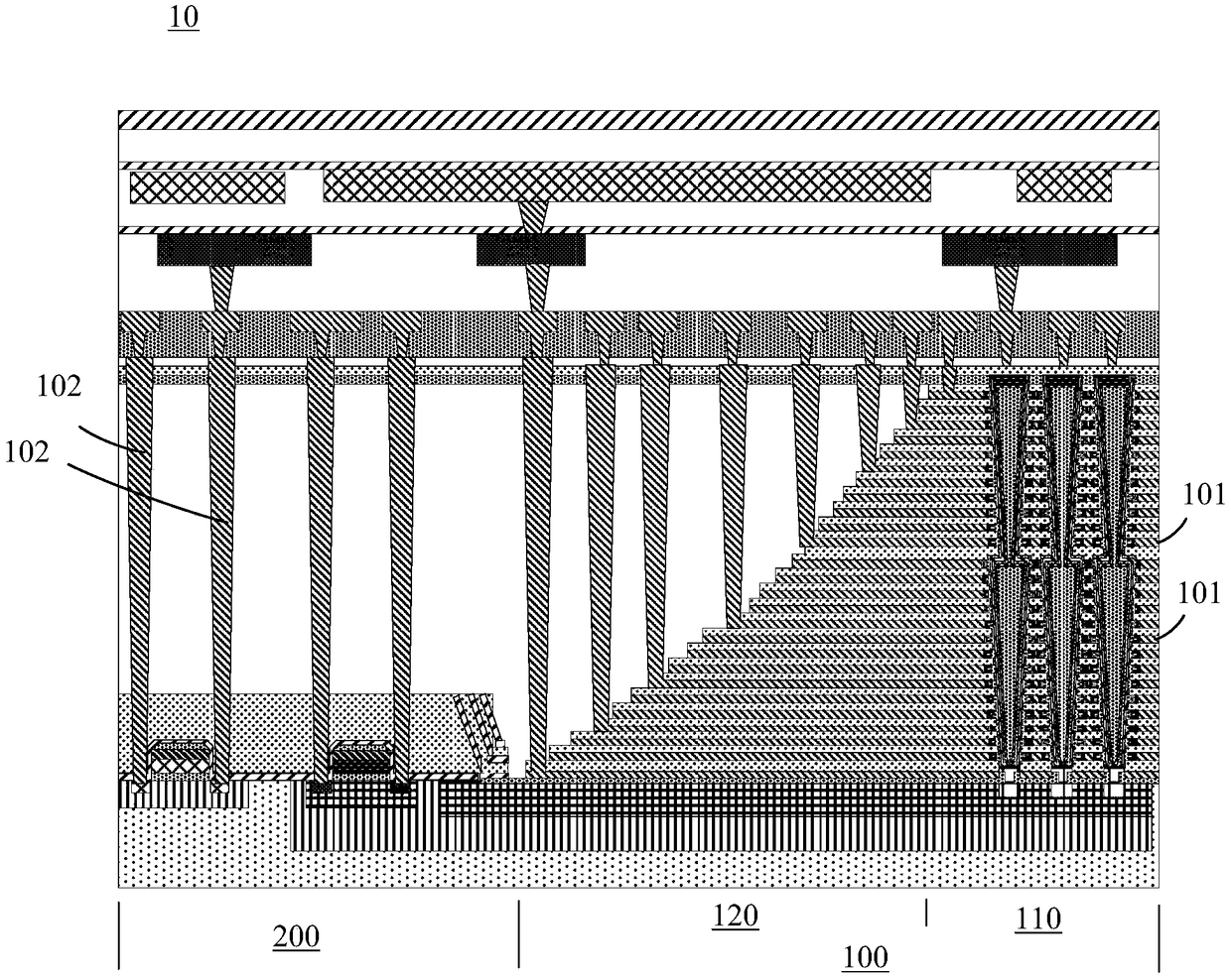
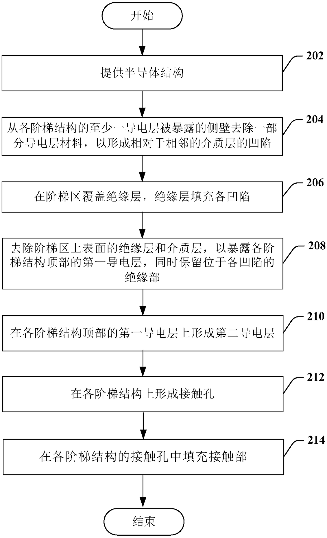
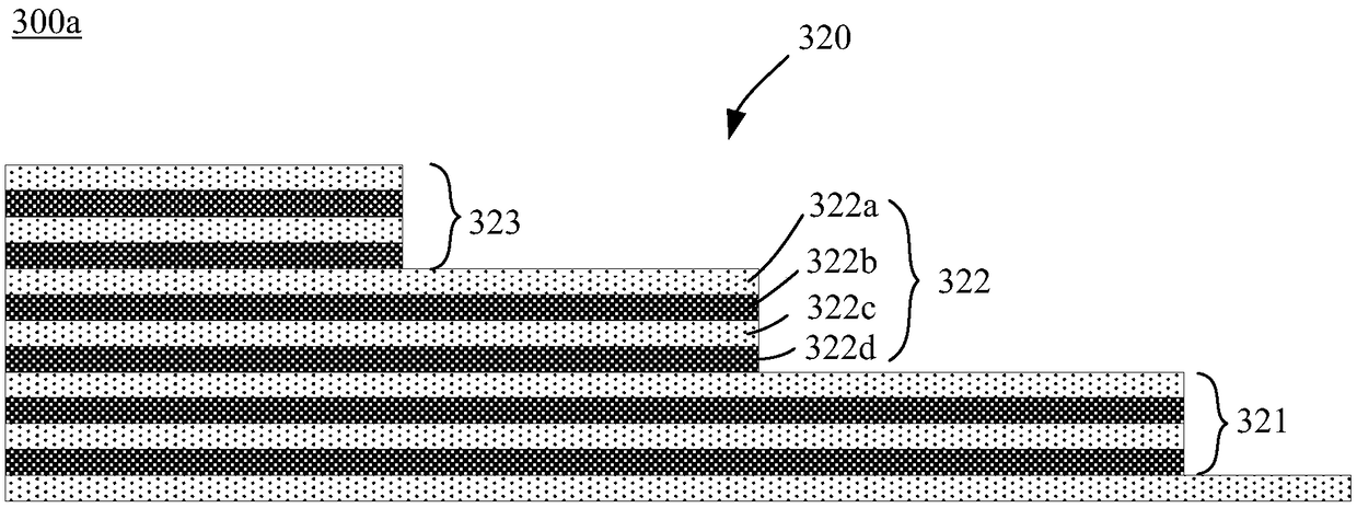
[0031] In order to make the above objects, features and advantages of the present invention more comprehensible, specific implementations of the present invention will be described in detail below in conjunction with the accompanying drawings.

[0032] In the following description, many specific details are set forth in order to fully understand the present invention, but the present invention can also be implemented in other ways than those described here, so the present invention is not limited by the specific embodiments disclosed below.

[0033] As indicated in this application and claims, the terms "a", "an", "an" and / or "the" do not refer to the singular and may include the plural unless the context clearly indicates an exception. Generally speaking, the terms "comprising" and "comprising" only suggest the inclusion of clearly identified steps and elements, and these steps and elements do not constitute an exclusive list, and the method or device may also contain other st...


PUM


Abstract

The invention provides a method for forming a contact hole in a step region of a three-dimensional storage device. The method comprises the following steps of providing a semiconductor structure, wherein the semiconductor structure has a step region, the step region has a plurality of step structures, and each step structure comprises at least one medium layer and at least one conducting layer inalternate stacking from top to bottom; removing a part of conducting layer material from the exposed side wall of at least one conducting layer of each step structure so as to form recessed parts opposite to the adjacent medium layers; covering an insulation layer in the step region; filling each recessed part by the insulation layer; removing the medium layer and the insulation layer on the uppersurface of the step region so as to expose the first conducting layer on the top of each step structure; meanwhile, remaining the insulation layer positioned at each recessed part; forming a second conducting layer on the first conducting layer on the top of each step layer; forming the contact hole on each step structure. The thickness of the conducting layer on the step region is increased, sothat greater allowance can be provided for the etching of the contact hole, so that the contact hole etching penetration probability is reduced.

Description

technical field [0001] The invention mainly relates to a semiconductor manufacturing method, in particular to a method for forming a contact hole in a step region of a three-dimensional memory device, and the three-dimensional memory device. Background technique [0002] In order to overcome the limitations of two-dimensional memory devices, the industry has developed memory devices with a three-dimensional (3D) structure to increase integration density by three-dimensionally arranging memory cells on a substrate. [0003] In a three-dimensional memory device such as 3D NAND flash memory, a memory array may include a core region and a stair region. The stepped area is used to lead out contacts for the control gates in each layer of the memory array. These control gates are used as word lines of the memory array to perform operations such as programming, erasing and writing, and reading. [0004] In the manufacturing process of 3D NAND flash memory, contact holes are formed...

Claims


Application Information

Patent Timeline
Patent Type & Authority Applications(China)
IPC IPC(8): H01L27/11524H01L27/11551
CPCH10B41/20H10B41/35
Inventor 刘峻
Owner YANGTZE MEMORY TECH CO LTD
Why Eureka
Try Eureka