Working method of a sheet metal cutting device

A cutting device and working method technology, applied in metal processing, metal processing equipment, metal processing machinery parts, etc., can solve problems such as worker injury, increase processing cost in processing steps, and generate a large amount of labor, reduce labor, simple structure, The effect of low equipment cost

Active Publication Date: 2020-07-17
TANGSHAN HONGLI HARDWARE TOOLS
View PDF5 Cites 0 Cited by
  • Summary
  • Abstract
  • Description
  • Claims
  • Application Information

AI Technical Summary

Problems solved by technology

[0002] The metal plate is cut according to the size specification alignment during the processing. The existing metal plate cutting device can realize the automatic cutting of the metal plate, but there are still many problems in the cutting of the existing metal plate cutting device. First, when cutting the metal plate When the fixed-distance cutting of the metal plate cannot be effectively realized, workers usually need to cooperate with the work to adjust the position of the metal plate or adjust the device to achieve the fixed-distance cutting of the metal plate. Secondly, in the cutting process, a large number of waste, and the waste is splashed around under the drive of the cutting wheel, which is easy to cause injury to workers. In addition, when cutting metal plates, it is necessary to inject water into the cutting wheel to cool down the cutting wheel. After use, there will be a lot of Metal waste, so most of the existing cooling mechanisms do not directly circulate the cooling water, and the cooling water is treated uniformly after processing, which increases the processing steps and processing costs

Method used


Image

  • Working method of a sheet metal cutting device
  • Working method of a sheet metal cutting device
  • Working method of a sheet metal cutting device

Examples


Embodiment Construction

[0030] The following will be combined with Figure 1 to Figure 10 The present invention is described in detail, and the technical solutions in the embodiments of the present invention are clearly and completely described. Apparently, the described embodiments are only some of the embodiments of the present invention, not all of them. Based on the embodiments of the present invention, all other embodiments obtained by persons of ordinary skill in the art without making creative efforts belong to the protection scope of the present invention.

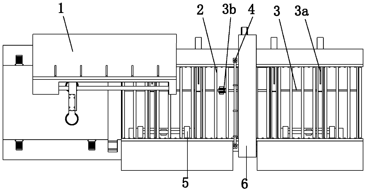
[0031] The present invention provides a kind of working method of sheet metal cutting device by improving here, as Figure 1-Figure 10As shown, it includes a feeding mechanism 1, a conveyor belt 2, a limiting mechanism 3, a positioning mechanism 4, a blanking mechanism 5 and a cutting mechanism 6. The feeding mechanism 1 is located at one end of the conveyor belt 2, and the limiting mechanism 3 is installed on On both sides of the convey...


PUM


Abstract

The invention relates to the field of plate processing, in particular to a working method of a metal plate cutting device. The metal plate cutting device comprises a loading mechanism, a conveyor belt, limiting mechanisms, a positioning mechanism, an unloading mechanism and a cutting mechanism, the loading mechanism is located at one end of the conveyor belt, the limiting mechanisms are mounted onthe two sides of the conveyor belt, the positioning mechanism and the cutting mechanism are both located above the middle part of the conveyor belt, the unloading mechanism is mounted below the conveyor belt, the loading mechanism comprises a lifting assembly and a loading assembly, the lifting assembly is mounted at one end of the conveyor belt, the loading assembly is mounted above the liftingassembly, the cutting mechanism comprises a cutting assembly and a cooling assembly, the cooling assembly is mounted by the side of the cutting assembly, the limiting mechanisms comprise limiting assemblies and driving assemblies, and all the driving assemblies are mounted below the limiting assemblies. The metal plate cutting device has the beneficial effects that the metal plate can be cut for many times at controlled intervals, the workload of workers is relieved, and the working efficiency is improved; and the cooling water can be repeatedly used, and consumption of water resources is reduced.

Description

technical field [0001] The invention relates to the field of plate processing, in particular to a working method of a metal plate cutting device. Background technique [0002] The metal plate is cut according to the size specification alignment during the processing. The existing metal plate cutting device can realize the automatic cutting of the metal plate, but there are still many problems in the cutting of the existing metal plate cutting device. First, when cutting the metal plate When the fixed-distance cutting of the metal plate cannot be effectively realized, workers usually need to cooperate with the work to adjust the position of the metal plate or adjust the device to achieve the fixed-distance cutting of the metal plate. Secondly, in the cutting process, a large number of waste, and the waste is splashed back and forth under the drive of the cutting wheel, which is easy to cause injury to workers. In addition, when cutting metal plates, it is necessary to inject ...

Claims


Application Information

Patent Timeline
Patent Type & Authority Patents(China)
IPC IPC(8): B23Q7/00B23Q11/10B23Q1/26
CPCB23Q1/26B23Q7/00B23Q11/10
Inventor 李启同赵一张华
Owner TANGSHAN HONGLI HARDWARE TOOLS
Why Eureka
Try Eureka