Roughening-free construction method and mould for precast hollow slab girder

A hollow plate beam, chisel-free technology, applied in the direction of manufacturing tools, molds, unloading devices, etc., can solve the problems of easily destroying the plate beam structure, difficulty in manual or mechanical chiseling, uneven distribution of chiseling hair, etc. Gross process, shortening the casting and installation cycle of slab beams, and the effect of a wide range of applications

Active Publication Date: 2018-11-30
北京中兴恒工程咨询有限公司
View PDF4 Cites 8 Cited by
  • Summary
  • Abstract
  • Description
  • Claims
  • Application Information

AI Technical Summary

Problems solved by technology

In order to make the slab girder and the hinged concrete bond tightly, the surface of the slab girder is generally chiseled after the prefabricated formwork is removed. It is difficult to chisel the surface of the slab girder, whether it is manual or mechanical, and the chisel is unevenly distributed and easy to damage Plate beam structure

Method used


Image

  • Roughening-free construction method and mould for precast hollow slab girder
  • Roughening-free construction method and mould for precast hollow slab girder
  • Roughening-free construction method and mould for precast hollow slab girder

Examples


Embodiment 1

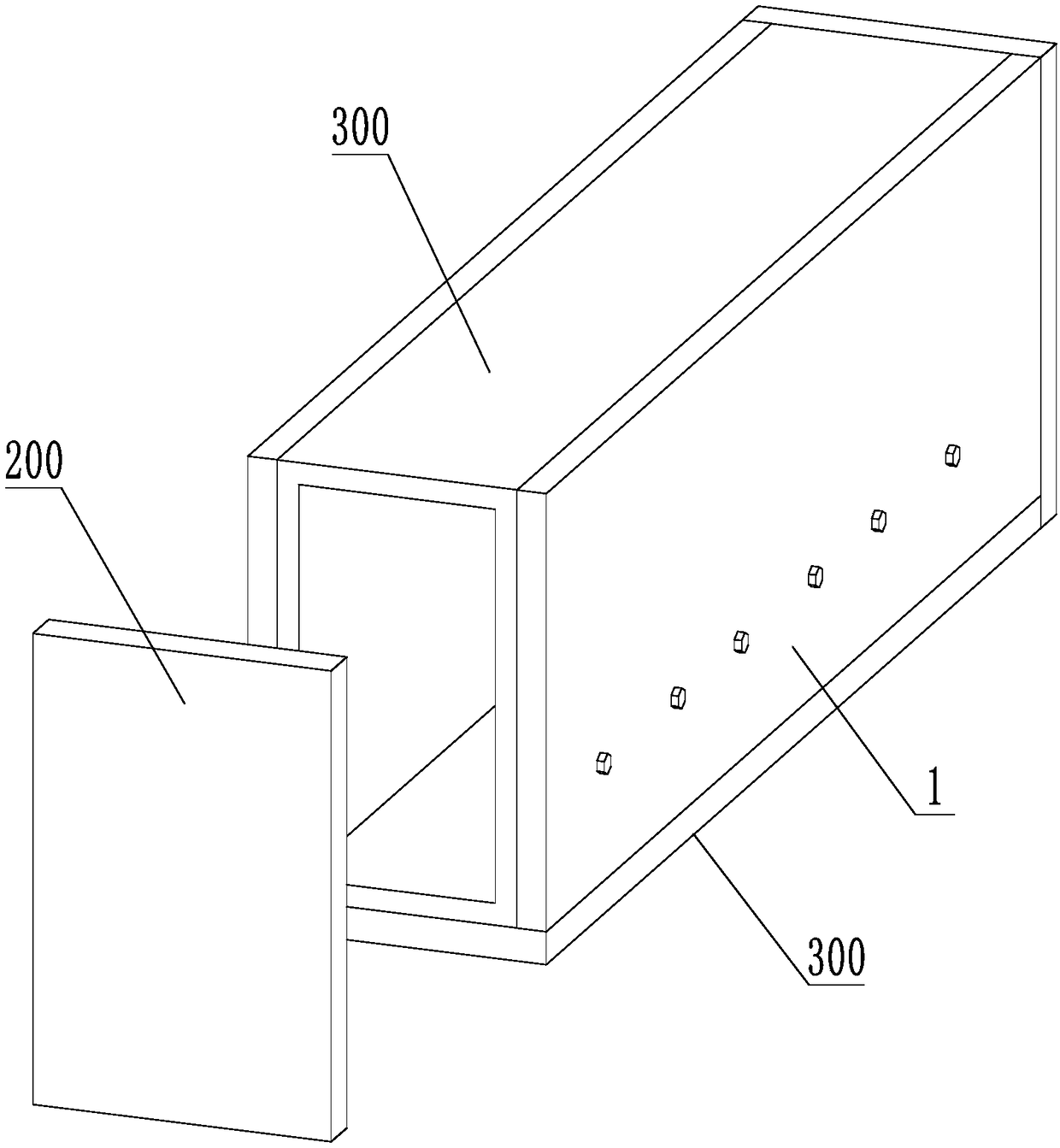
[0040] A prefabricated hollow slab beam free of chiseling construction mold, as attached figure 1 As shown, the mold is mainly composed of bottom formwork 100 at the bottom, end formwork 200 at both ends of the mold length direction, and side formwork 1 on both sides to form a mold with an upper opening. An inner mold is also arranged inside the plate girder 300 .

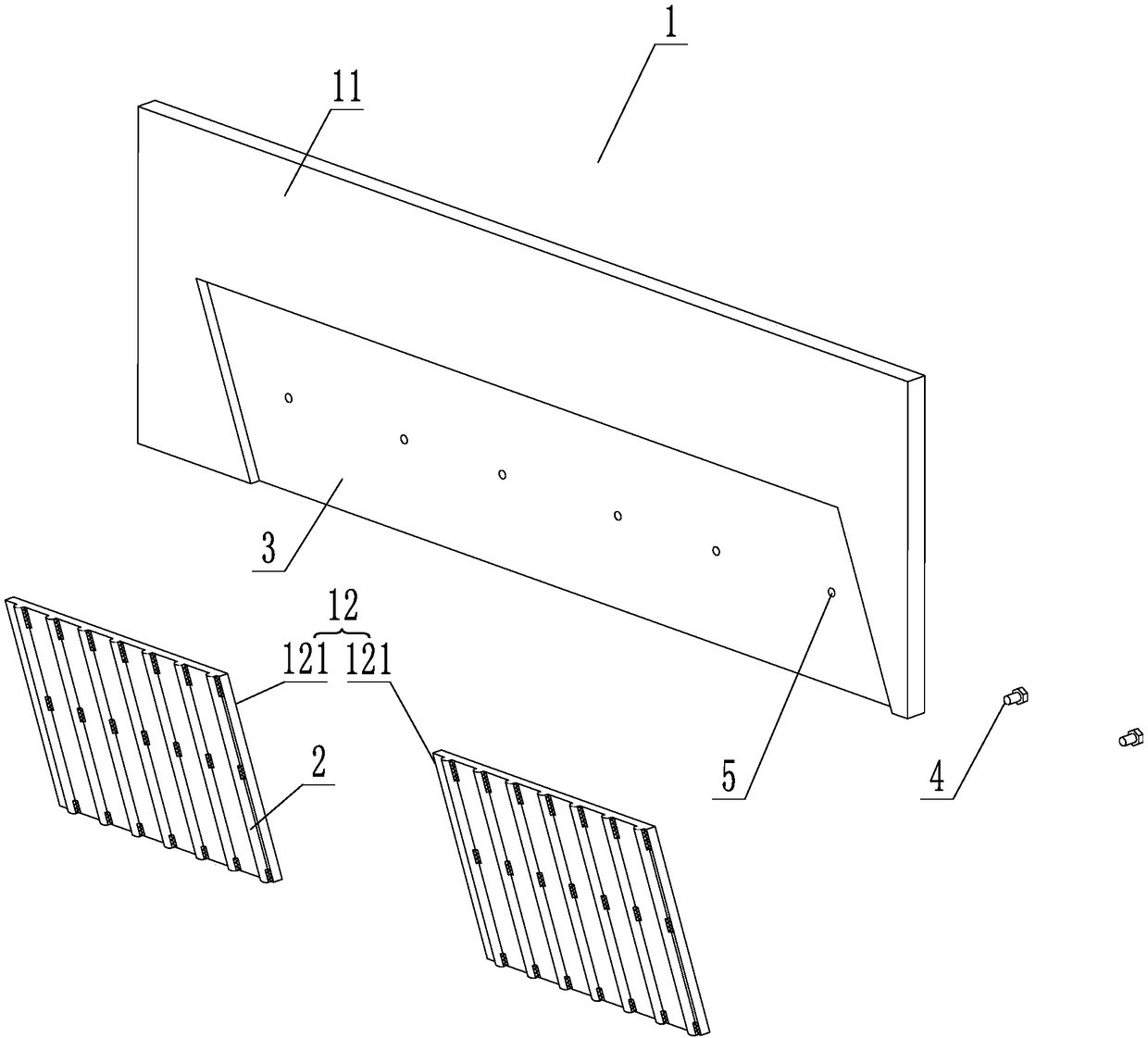
[0041] as attached figure 2 As shown, the side formwork 1 is formed by connecting the outer panel 11 and the inner lining panel 12, wherein the inner lining panel 12 is detachably connected to the inner side of the outer panel 11, which facilitates the disassembly and replacement of the inner lining panel 12. The outer plate 1 is a rectangular plate, and the lower part of its inner surface is provided with a parallelogram-shaped groove 3, the groove 3 extends along the length direction of the outer plate 11, and the inner lining plate 12 is composed of a plurality of single plates 121 of equal size. less than th...

Embodiment 2

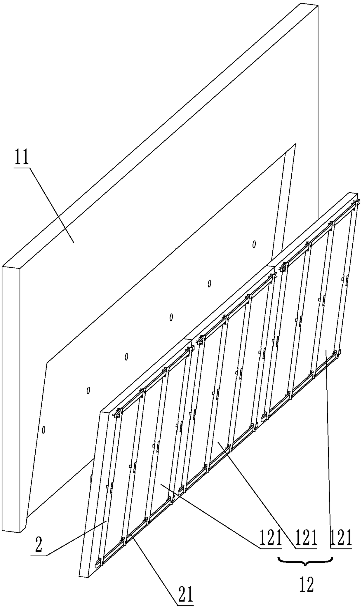
[0046] as attached image 3 and 4As shown, a plurality of ribs 2 are rotatably connected to the middle position of the inner surface of each single plate 121 of the inner liner 12, and the rotation axis of the ribs 2 is set in the middle of the ribs 2, and is located at the same position on the single plate 121. level height. In the present embodiment, the rib 2 adopts a plurality of equal-length metal rods, pointing to the upper and lower sides of the veneer 121, the length of the rib 2 is equal to the height of the veneer 121, and the rib 2 rotates, so that the upper and lower ends of the rib 2 will not move from the single plate 121. The upper and lower sides of the plate 121 protrude; the convex ribs 2 are equally spaced on the single plate 121, and the distance between the rotation axes of adjacent convex ribs 2 is 100mm.

[0047] The upper and lower ends of the ribs 2 on each veneer 121 are hinged with a connecting rod 21, and the connecting rod 21 is hinged with all t...


PUM

PropertyMeasurementUnit
heightaaaaaaaaaa

Abstract

The invention relates to a roughening-free construction method and mould for a precast hollow slab girder, relates to the field of bridge building construction, and solves the problem that the surfaceof the precast hollow slab girder is difficultly roughened. The roughening-free construction mould comprises a bottom formwork of a rectangular groove structure with an opening in the upper end, an end formwork and a lateral formwork, wherein the lateral formwork comprises an external plate and a plurality of inner lining plates which are detachably connected to the inner side of the external plate, a plurality of paralleled protruding ribs which make contact with the surface of the precast hollow slab girder are arranged on the inner surfaces of the inner lining plates, grooves are formed inthe inner side face of the external plate, the inner lining plates are inserted into the grooves and are flush with the surface of the external plate, and locking bolts penetrate through the externalplate from the outer side face to the inner side face and are in threaded connection with the inner lining plates. In the slab girder precasting stage, roughening is conducted, grooved rough surfaceswhich are uniformly distributed are formed, and construction is simple.

Description

technical field [0001] The invention relates to the field of bridge construction, in particular to a chiseling-free construction method and mold for a prefabricated hollow slab beam. Background technique [0002] Bridge prefabricated hollow slab girder bridge has the advantages of simple structure, economical materials, convenient prefabrication, easy standardized production and construction, convenient transportation and hoisting, etc., and is widely used. The horizontal connection between the prefabricated hollow slab girders is mainly realized by post-cast concrete hinge joints, the purpose of which is to distribute the local load acting on the driveway slab to each slab girder to bear jointly, realize the cooperative work of multiple slabs, and avoid damage to the structure. Unfavorable veneer stress phenomenon. In order to make the slab girder and the hinged concrete bond tightly, the surface of the slab girder is generally chiseled after the prefabricated formwork is ...

Claims


Application Information

Patent Timeline
Patent Type & Authority Applications(China)
IPC IPC(8): B28B7/22B28B23/02B28B13/04
CPCB28B7/22B28B13/04B28B23/02
Inventor 边瑞明张建琴李清春张庆边晓彤胡双豫陈淑慧曹伟宏
Owner 北京中兴恒工程咨询有限公司
Why Eureka
Try Eureka