Anti-blocking type mould and production process for mould

A mold and anti-blocking technology, which is applied in the field of foam molding, can solve the problems of affecting the surface quality of plastic parts, slow molding speed of plastic parts, and uneven heating of foamed plastics, so as to save steam costs, shorten foaming molding time, increase large area effect

Inactive Publication Date: 2018-11-30
칭다오탠윤헝왠폼플라스틱머쉬너리앤드이콰이먼트
View PDF5 Cites 2 Cited by
  • Summary
  • Abstract
  • Description
  • Claims
  • Application Information

AI Technical Summary

Problems solved by technology

However, when the existing mold is used, there are two problems: first, because there is a relatively long distance between the surfaces of the air holes 11, there is a gap between the plastic particles expanded during the foaming process and the wall of the mold 1. The residual air void volume is formed between them, and these void volumes lead to more porous structures on the surface of the molded plastic parts, which affects the surface quality of the plastic parts; Scaling and clogging of the steam mesh 12 affect the use; third, due to the small aperture of the steam mesh 12, the distribution of the ventilation holes 2 is scattered, and when the steam enters the mold cavity, it is multi-point local inflow, resulting in local foaming of the foamed plastic. Uneven heating, which leads to slower molding of plastic parts
However, there is still the problem that some of the steam meshes are blocked and difficult to remove when the plastic particles are foamed and formed.

Method used


Image

  • Anti-blocking type mould and production process for mould
  • Anti-blocking type mould and production process for mould
  • Anti-blocking type mould and production process for mould

Examples


Embodiment 1

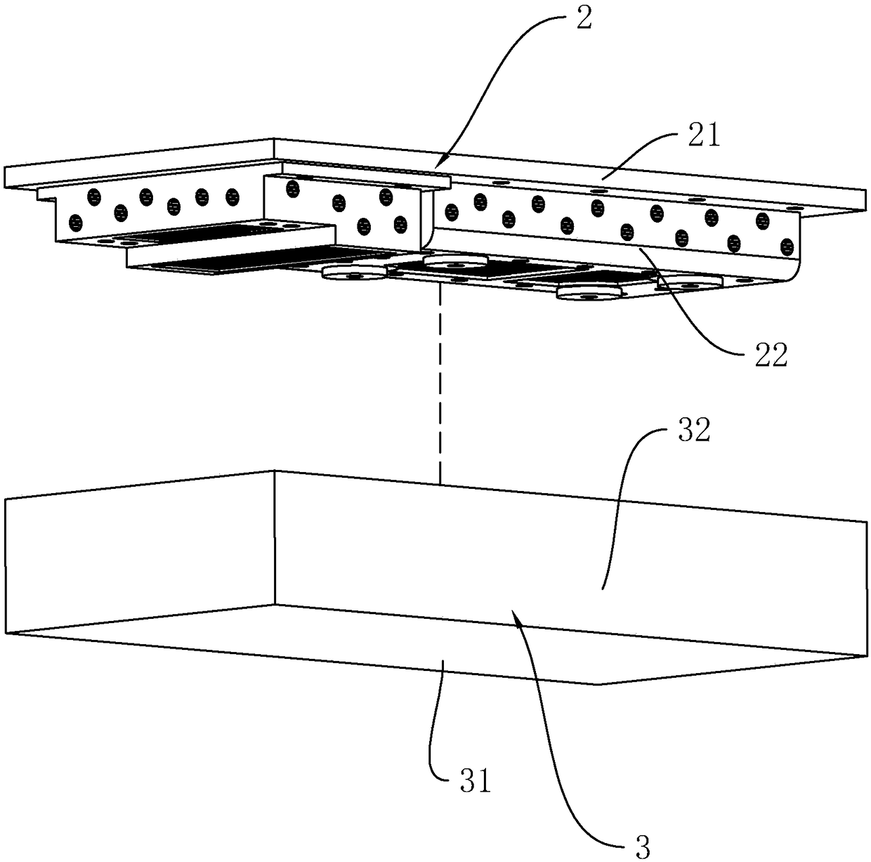
[0062] Embodiment 1: A kind of anti-blocking mold, combined with image 3 , including an upper mold 2 and a lower mold 3 used in conjunction with the upper mold 2 .

[0063] The upper mold 2 includes a horizontally arranged upper support plate 21 and two punches 22 arranged on the lower surface of the upper support plate 21 . The lower mold 3 includes a lower bottom plate 41 and a frame body 32 vertically and fixedly connected to the upper surface of the lower supporting plate 31 . During work, the two punches 22 of the upper die 2 are placed in the frame body 32, and the upper end of the frame body 32 of the lower die 3 abuts against the lower surface of the upper support plate 21 of the upper die 2, so that the upper die 2 and the upper die 2 are in contact with each other. A molding cavity for molding foamed plastics is formed between the lower molds 3 .

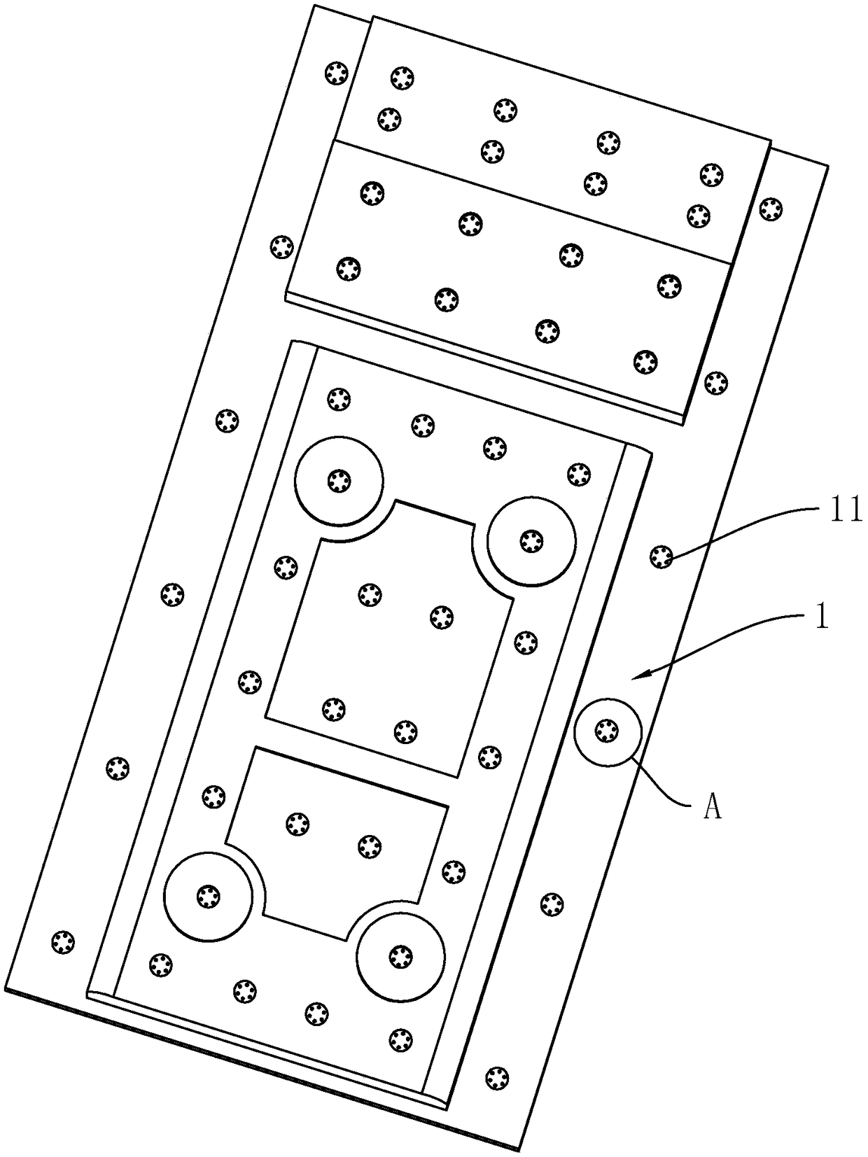
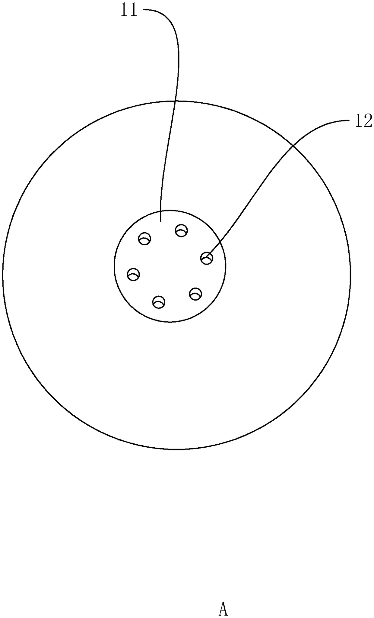
[0064] combine Figure 4 and Figure 5 , the upper support plate 21 and the punch 22 are respectively provided with...

Embodiment 2

[0067] Embodiment two: a kind of anti-clogging mold, combine Figure 7 , the difference from Embodiment 1 is that: the side wall of the punch 22 is also provided with a second through groove 222, and the second through groove 222 is also fixedly connected with a grid plate 24, and the grid plate in the second through groove 222 The length direction of the grid strips 241 of 24 is parallel to the lower surface of the upper support plate 21 .

[0068] Compared with Embodiment 1, the advantage is that: by opening the second through groove 222 on the side wall of the punch 22 and fixedly connecting the grid plate 24, the steam entering the molding cavity from the side wall of the punch 22 can be further increased. speed, so that the foamed plastic in the molding cavity is evenly heated, and then the foamed plastic on the side wall of the punch 22 and the foamed plastic on the bottom of the punch 22 are foamed and molded synchronously.

Embodiment 3

[0069] Embodiment three: a kind of anti-clogging mold, combined Figure 8 , and the difference from the second embodiment is that: the length direction of the grid bar 241 in the second through groove 222 is the same as the drawing direction of the punch 22 .

[0070] Compared with implementation one, the advantage is: the length direction of the grid bar 241 in the second through groove 222 is the same as the drawing direction of the punch 22, and when the convex film is pulled out, the amount of foaming plastic and the punch 22 can be reduced. The frictional force is convenient for the drafting of punch 22.


PUM


Abstract

The invention discloses an anti-blocking type mould and a production process for the mould, and relates to the technical field of foam-plastic forming. The anti-blocking type mould comprises an uppermould and a lower mould, wherein the upper mould and the lower mould are mutually matched to form a forming cavity; and a plurality of strip-shaped seams for allowing steam to enter the forming cavityare formed in the upper mould. The anti-blocking type mould solves the problem that needle eye shaped gas inlets of the conventional mould are easily blocked to affect use when high-temperature steampasses through the mould for foaming and forming foam-plastic particles, can prolong continuous working time of the mould, reduces labor intensity of maintaining the mould, and increases a productionrate.

Description

technical field [0001] The invention relates to the technical field of foam molding, in particular to an anti-blocking mold and a production process of the mold. Background technique [0002] Foam plastic mold, also known as plastic foam mold, is a molding device installed on a foam plastic molding machine. The foam plastic molding machine is a polystyrene foam molding equipment commonly used in China. There are two types of molding machines. Thick foam plastic parts or large and medium-sized foam plastic parts are often directly foamed by a foam plastic molding machine. There are vent holes with a diameter of 0.1~0.4mm on the mold for ventilation. Before molding, 0.1~0.2MPa heating steam is passed through. After the mold is preheated for 0.5min, the air outlet is opened, and the pre-fired The foam particles are injected into the mold cavity, the air outlet is closed, and 0.1~0.2MPa steam is introduced into the steam chamber to raise the temperature to about 110°C, the pre...

Claims


Application Information

Patent Timeline
Patent Type & Authority Applications(China)
IPC IPC(8): B29C44/58B29C33/38B23P15/24
CPCB23P15/24B29C33/3842B29C44/58B22C13/00B29C33/10B29C33/42B29C44/588
Inventor 金相云
Owner 칭다오탠윤헝왠폼플라스틱머쉬너리앤드이콰이먼트
Why Eureka
Try Eureka