
Pre-cooling type air inlet and hypersonic speed aircraft

An air inlet and pre-cooling technology, which is applied to the combustion of the air inlet of the power unit, aircraft parts, and power units on the aircraft, etc., can solve the problems of heavy engine weight, complex structure, and large pressure loss, and improve the compression efficiency. and pressure ratio, increase the heat exchange area, improve the effect of heat exchange efficiency

Active Publication Date: 2018-11-30
NAT UNIV OF DEFENSE TECH
View PDF6 Cites 8 Cited by
  • Summary
  • Abstract
  • Description
  • Claims
  • Application Information

AI Technical Summary

Problems solved by technology

[0009] The invention provides a pre-cooling air inlet and a hypersonic aircraft, which are used to overcome the defects of complex structure, heavy engine weight, and large pressure loss in the prior art. Improve airflow compression efficiency

Method used


Image

  • Pre-cooling type air inlet and hypersonic speed aircraft
  • Pre-cooling type air inlet and hypersonic speed aircraft
  • Pre-cooling type air inlet and hypersonic speed aircraft

Examples


Embodiment 1

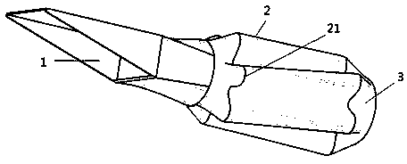
[0036] Please refer to figure 1 , the present invention provides a pre-cooling air inlet, including an inlet section 1, a pre-cooling section 2 and a transition section 3 connected in sequence, wherein:

[0037] The inlet section 1 is used for inhaling airflow; the bottom has an air inlet, and the two sides are wedge-shaped;

[0038] The pre-cooling section 2 is in the shape of a cylinder, and a plurality of distribution channels 21 are distributed in the circumferential direction for the incoming gas to rotate according to a preset angle. All the distribution channels 21 are connected to each other. The depth of the distribution channels 21 is The direction is along the radial direction of the cross-section of the pre-cooling section; the inner wall of the pre-cooling section 2 has a number of convex heat exchange cells 23, and a cooling channel for the circulation of the cooling medium is formed between the outer wall and the inner wall of the pre-cooling section 22. The le...

Embodiment 2

[0051] Please refer to Figure 7 , and the difference from Embodiment 1 is that the distribution channel 21 is in a rotating shape along the radial direction of the pre-cooling section 3 and rotates in the same direction. Radial rotation through the shunt channel 21 (see Figure 7 Arrow direction) to form a pre-swirling airflow, which is suitable for inlets with large radial dimensions.

Embodiment 3

[0053] An embodiment of the present invention is also a hypersonic aircraft, including a compressor and the pre-cooling air inlet of any of the above embodiments, the transition section 3 of the pre-cooling air inlet is connected to the air inlet of the compressor. The beneficial effect is the same as that of the above-mentioned pre-cooling air intake channel, and will not be repeated here.


PUM


Abstract

The invention discloses a pre-cooling type air inlet and a hypersonic speed aircraft. The pre-cooling type air inlet comprises an inlet section, a pre-cooling section and a transition section which are sequentially connected, wherein the pre-cooling section is in a cylinder shape; the interior of the pre-cooling section is provided with a plurality of flow distribution passages which are used forenabling the incoming air to rotate at preset angles; the flow distribution passages are mutually communicated, and the depth direction of each flow distribution passage is the radial direction of thecross section of the pre-cooling section; the inner wall of the pre-cooling section is provided with a plurality of convex heat exchange micro-elements; a cooling passage is formed between the outerwall and inner wall of the pre-cooling section, and is used for a cooling medium to flow through. By adopting the plan, the pre-cooling type air inlet has the advantages that the problems of increasing of engine length and high loss of total pressure in the prior art are solved; the engine length is reduced, the loss of total pressure is reduced, and the efficiency of an air compressor is improved.

Description

technical field [0001] The invention relates to the technical field of hypersonic aircraft, in particular to a precooling air inlet and a hypersonic aircraft. Background technique [0002] It can be seen from the principle of the engine that the unit thrust of the engine increases with the increase of the pressure ratio of the compressor, and a higher unit thrust is easy to achieve a higher flight speed. Under the condition of Mach number < 3, the existing aero turbine engine is the ideal flight power; when the flight Mach number is > 3, the compressor exhaust temperature will exceed the high temperature range of the blade due to the increase of the compressor pressure ratio under high speed conditions , resulting in sharp deterioration of engine performance and reduced reliability, which has become a bottleneck limiting the increase in engine speed. One of the effective ways to solve this problem is to reduce the intake temperature of high-speed airflow through the p...

Claims


Application Information

Patent Timeline
Patent Type & Authority Applications(China)
IPC IPC(8): B64D33/02
CPCB64D33/02B64D2033/024B64D2033/026B64D2033/0273
Inventor 刘俊兵范晓樯陶渊熊冰蒙泽威王翼刘卫东陈镜帆
Owner NAT UNIV OF DEFENSE TECH
Learn More