Heat pipe heating and fluid heating composite type pavement snow melting system and operation control method thereof

A heating system and composite technology are applied in the field of airport pavement snow melting systems and their operation strategies, which can solve the problems of low snow removal efficiency, large pavement damage, and high energy consumption, and achieve environmentally friendly operation, reduce operating costs, and have no energy consumption. Effect

Active Publication Date: 2018-11-30
HARBIN INST OF TECH +1
View PDF6 Cites 5 Cited by
  • Summary
  • Abstract
  • Description
  • Claims
  • Application Information

AI Technical Summary

Problems solved by technology

[0007] The purpose of the present invention is to solve the problems of low snow removal efficiency, serious environmental pollution, large road surface damage and large energy consumption in the existing airport snow removal method, and the problem of large energy consumption in the traditional electric heating method, and then provide a Heat pipe heating and fluid heating combined pavement snow melting system and its operation control method

Method used


Image

  • Heat pipe heating and fluid heating composite type pavement snow melting system and operation control method thereof
  • Heat pipe heating and fluid heating composite type pavement snow melting system and operation control method thereof
  • Heat pipe heating and fluid heating composite type pavement snow melting system and operation control method thereof

Examples


specific Embodiment approach 1

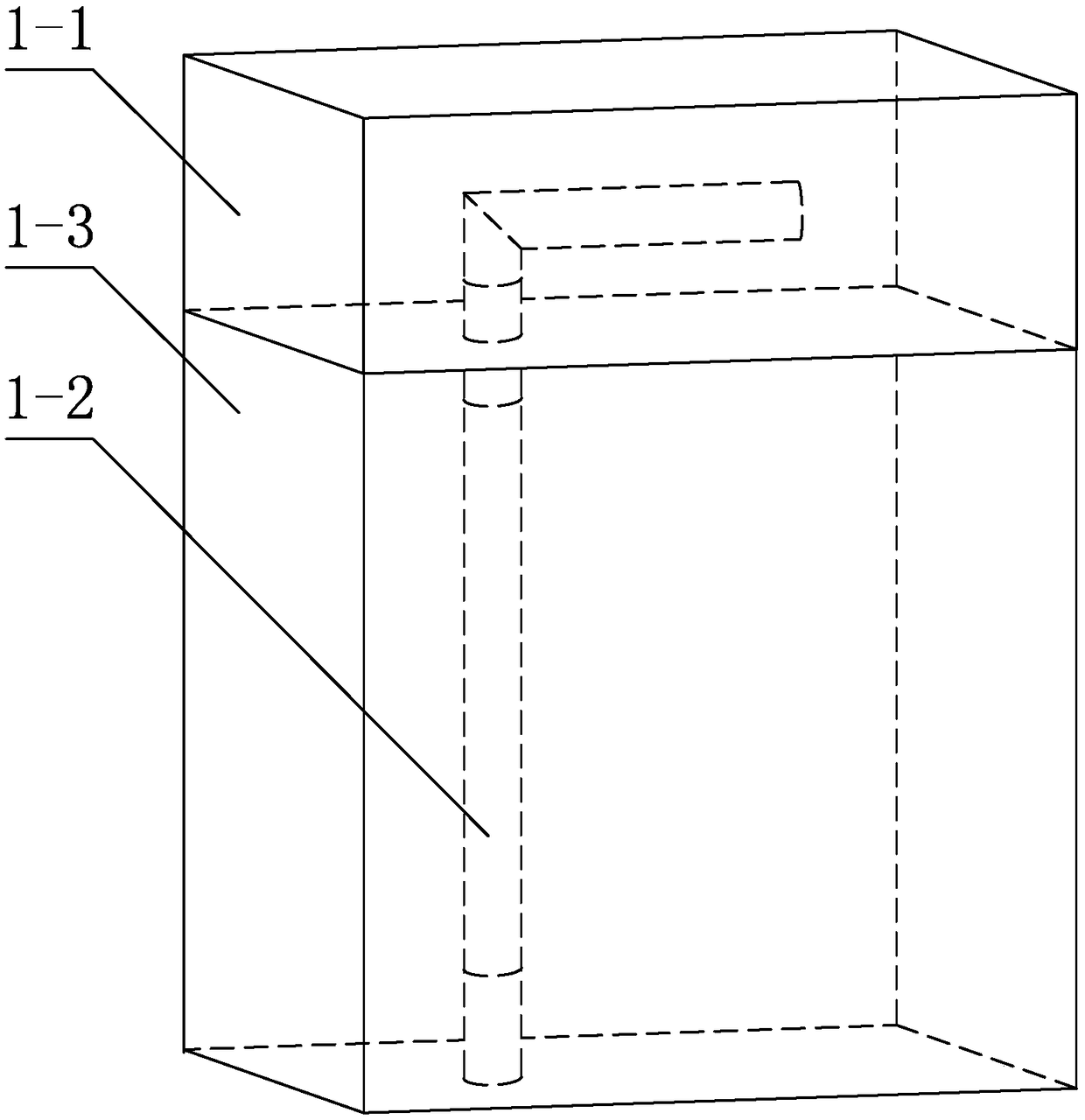
[0044] Specific implementation mode one: combine Figure 1 to Figure 5 Describe this embodiment mode, a heat pipe heating and fluid heating composite pavement snow melting system of this embodiment, the snow melting system includes a pavement structure layer 1-1 and an underground soil layer 1-3, it also includes a heat pipe heating system and a fluid heating system Heating system;

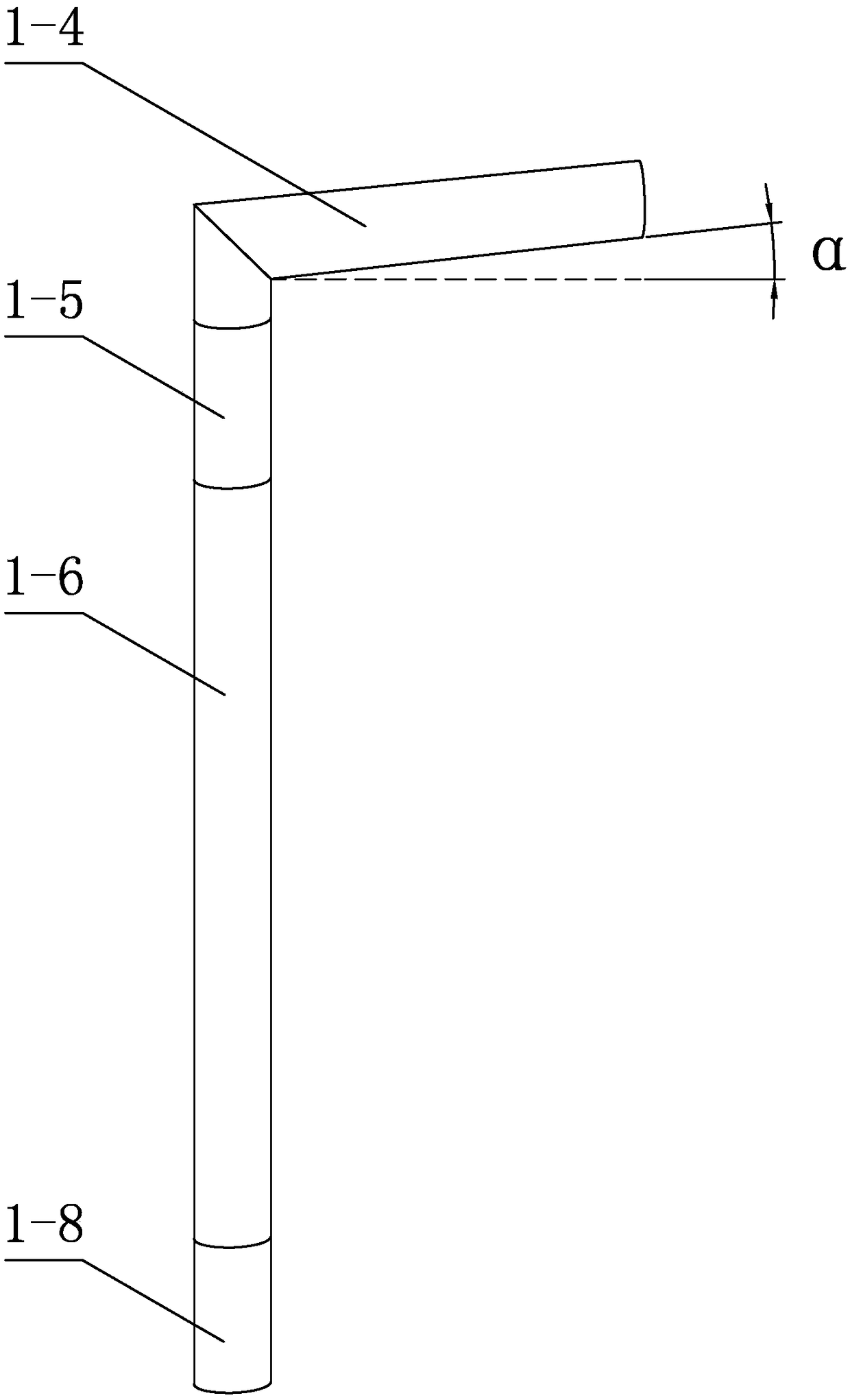
[0045] The heat pipe heating system includes multiple gravity heat pipes 1-2, which are arranged in parallel inside the pavement structure layer 1-1 and the underground soil layer 1-3, and each gravity heat pipe 1-2 includes condensation Sections 1-4, adiabatic section 1-5, evaporating section 1-6, and liquid storage tank 1-8, condensing section 1-4, adiabatic section 1-5, and evaporating section 1-6 are connected sequentially from top to bottom, condensing Section 1-4 is obliquely arranged inside the pavement structure layer 1-1, evaporation section 1-6 is vertically arranged inside the undergro...

specific Embodiment approach 2

[0050] Specific implementation mode two: combination Figure 4 To illustrate this embodiment, the heat pump unit 2-2 of the fluid heating system in this embodiment includes an evaporator 2-8, a condenser 2-9, an air compressor 2-10, a third control valve 2-11, and a condenser outlet pipe and the condenser water inlet pipe, the first inlet port of the evaporator 2-8 is communicated with the water outlet pipe 2-5 of the heat extraction system, the first outlet end of the evaporator 2-8 is communicated with the water inlet pipe 2-4 of the heat extraction system, and the evaporator The second inlet port of 2-8 communicates with the first outlet port of condenser 2-9 through the condenser water outlet pipe, and an air compressor is arranged on the condenser water outlet pipe between evaporator 2-8 and condenser 2-9 2-10, the second outlet port of the evaporator 2-8 communicates with the first inlet port of the condenser 2-9 through the condenser water inlet pipe, and the condenser ...

specific Embodiment approach 3

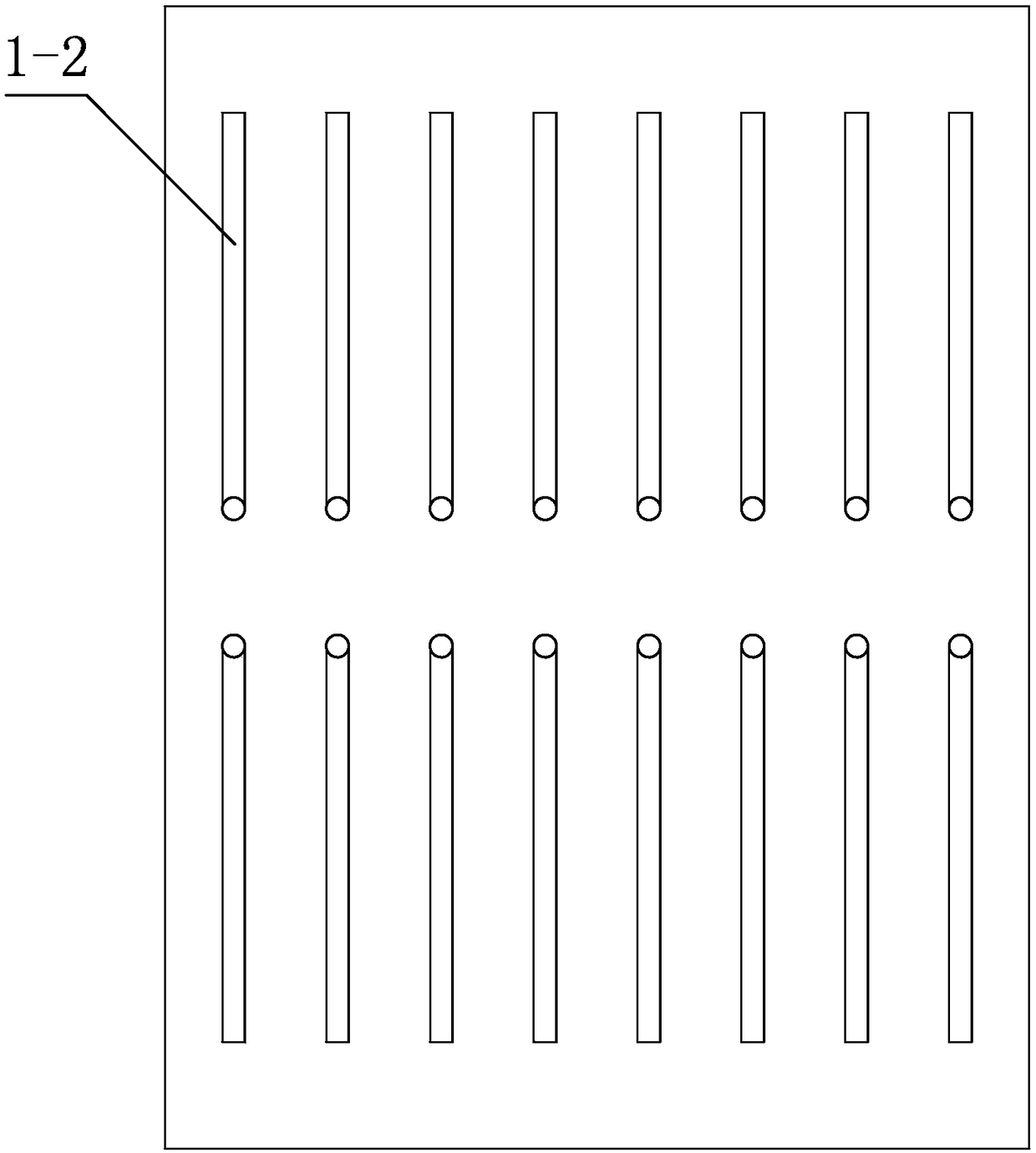
[0051] Specific implementation mode three: combination image 3 and Figure 5 To illustrate this embodiment, the road surface cooling pipes 2-3 of the fluid heating system of this embodiment are arranged inside the road surface structure layer 1-1 using S-shaped coils, and the multiple gravity heat pipes 1-2 of the heat pipe heating system are arranged on the The position between the heat pipes 2-3 on the road surface, the depth of the heat pipe 2-3 from the upper surface of the road structure layer 1-1 and the depth of the gravity heat pipe 1-2 from the upper surface of the road structure layer 1-1 are set in the same way, and the road surface The distance between the heat dissipation pipe 2-3 and the upper surface of the pavement structure layer 1-1 is 6-15cm in depth. The plurality of gravity heat pipes 1-2 exist independently. Due to the long surface size, in order to facilitate heat transfer, it is advisable to adopt the arrangement of double-row gravity heat pipes 1-2....


PUM


Abstract

The invention provides a heat pipe heating and fluid heating composite type pavement snow melting system and an operation control method thereof and relates to the technical field of airport pavementsnow melting systems and operation strategies. The problems of low snow removing efficiency, serious environment pollution, large pavement damage and large energy consumption of an existing airport pavement snow removing method are solved. Multiple gravity type heat pipes of a heat pipe heating system are placed in a pavement structural layer and an underground soil layer in parallel; a condensingsection, a heat insulating section and an evaporation section of each gravity type heat pipe are connected with each other in sequence from top to bottom; the condensing sections are obliquely placedin the pavement structural layer; the evaporation sections are vertically placed in the underground soil layer; liquid storage tanks are arranged at the lower parts of the evaporation sections; and afluid heating system comprises an underground heat taking system, a heat pump unit and a pavement system; the heat pump unit is positioned between the underground heat taking system and the pavementsystem. According to the heat pipe heating and fluid heating composite type pavement snow melting system, the operation cost of the fluid heating system is reduced; and meanwhile, the temperature application domain of the heat pipe heating system is expanded.

Description

technical field [0001] The invention relates to the technical field of an airport pavement snow melting system and its operation strategy, in particular to a heat pipe heating and fluid heating composite pavement snow melting system and an operation control method thereof. Background technique [0002] More than 100 airports in my country are in the snow belt. The problem of snow and icing on roads in winter has become the main factor restricting the safe operation of airports. The main reason is that the existence of the ice and snow layer reduces the friction coefficient between the tire and the road surface, which can easily cause flight accidents. [0003] Existing snow and ice removal technologies for airport pavement mainly adopt mechanical snow removal, chemical snow melting and electric heating snow melting and so on. Among them, the efficiency of mechanical snow removal method is low, and the removal is not thorough, and it is easy to generate a thin ice layer on ...

Claims


Application Information

Patent Timeline
Patent Type & Authority Applications(China)
IPC IPC(8): E01C11/26F24T10/10
CPCE01C11/26E01C11/265
Inventor 张驰徐慧宁谭忆秋苏新陈凤晨叶青付忠斌李广
Owner HARBIN INST OF TECH
Why Eureka
Try Eureka