Young modulus measurement method based on microscopic optical digital speckle method

A digital speckle and Young's modulus technology, applied in the engineering field, can solve the problems of wasting experiment time, heavy experiment workload, and high cost, and achieve the effect of reducing error value, simple steps, and convenient operation

A digital speckle and Young's modulus technology, applied in the engineering field, can solve the problems of wasting experiment time, heavy experiment workload, and high cost, and achieve the effect of reducing error value, simple steps, and convenient operation

CN108918271APending Publication Date: 2018-11-30SUZHOU UNIV

Image

  • Young modulus measurement method based on microscopic optical digital speckle method
  • Young modulus measurement method based on microscopic optical digital speckle method
  • Young modulus measurement method based on microscopic optical digital speckle method

Examples


Embodiment 1

[0036] Let A(x A ,y A ) is the center point of the reference sub-area, and the reference sub-area has been moved to A'(x A ',y A ') nearby locations. The displacement of the center point A is u in the x direction and y direction respectively A , v A ,which is:

[0037] x A '=x A + u A ;y A '=y A +v A

[0038] Let B(x B ,y B ) is any point in the sub-area, and the positional relationship between point B and the center point A is:

[0039] x B =x A +△x;y B =y A +△y

[0040]Among them, Δx and Δy are the distances from point B to point A in the x direction and y direction. If the sub-area is deformed, point B moves to B'(x B ',y B '), then:

[0041] x B '=x B + u B ;y B '=y B +v B

[0042] Among them, u B , v B is the displacement of point B. When △x and △y are small enough, the displacement of point B can be approximated by the displacement of its adjacent point A and its derivative:
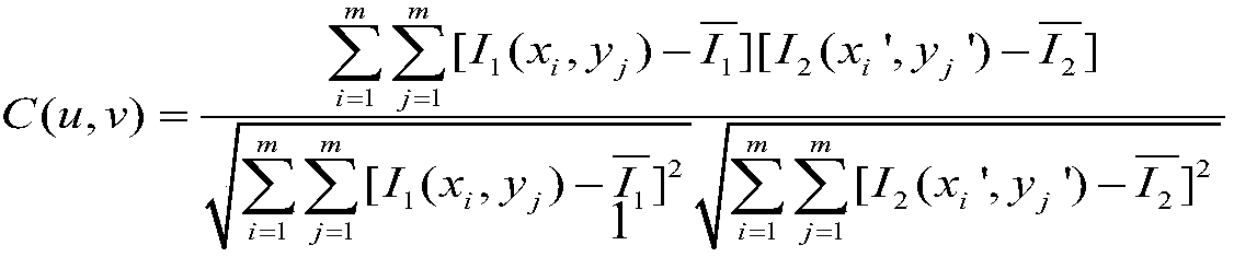
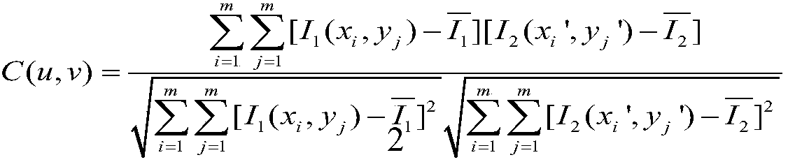
[0043]

[0044] Point B is any point in the sub-area. If (...

Embodiment 2

[0061] Provide experimental instruments, including: steel wire, metal support frame, vernier caliper, screw micrometer, meter ruler, weight, microscope objective lens, image CCD, and host PC.

[0062] Set the experimental parameters: the length of the steel wire is 475mm, and the cross-sectional area is 0.05725mm 2 , the theoretical value of Young's modulus is 200Gpa; a single weight is 320g, a total of 5.

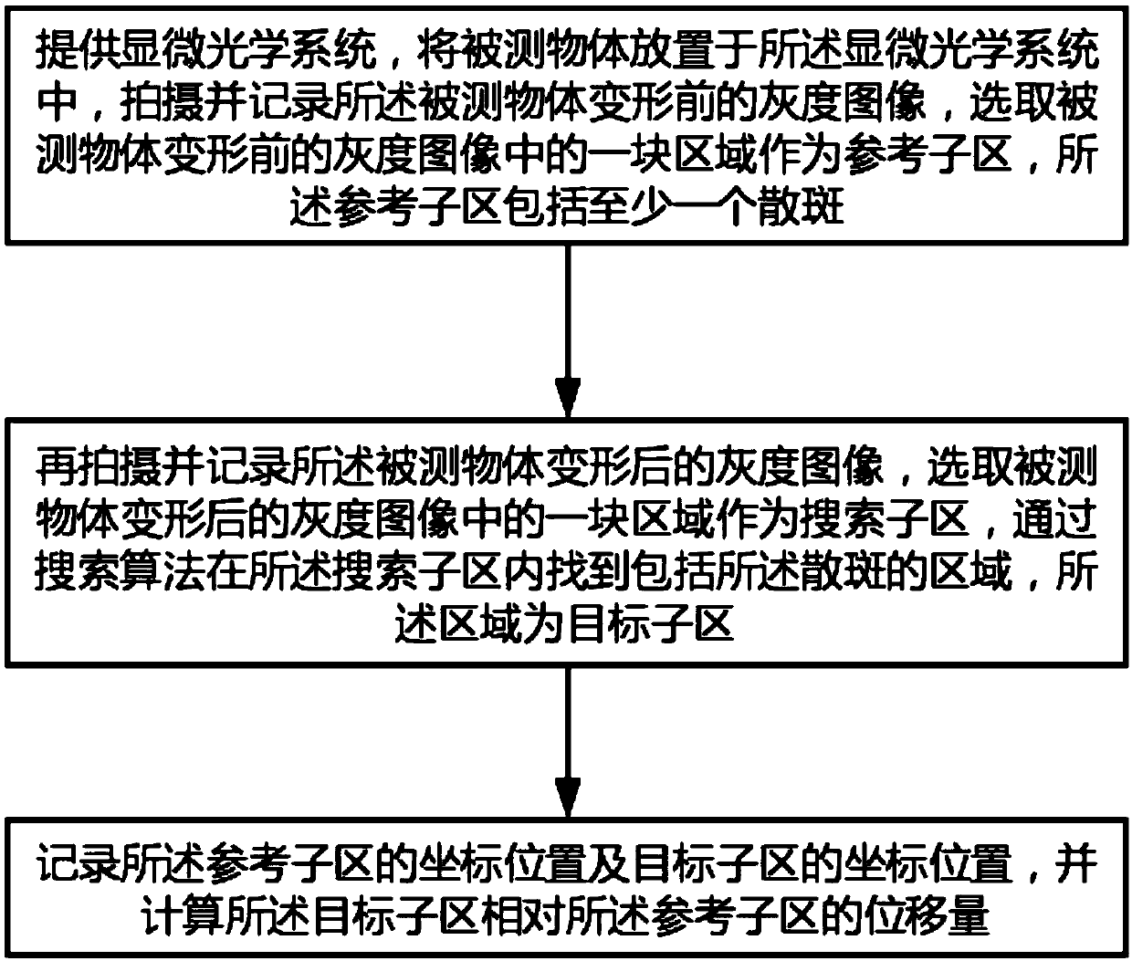
[0063] The functions of the above parts are as follows: the support frame is used to hang the steel wire, and a heavy object is hung on the lower end of the steel wire to make the steel wire stretch and deform; since the deformation reaches the micron level, it is difficult to observe, so the small deformation of the steel wire needs to be enlarged by the micro-optical system; Then, the CCD is used to collect image information; then, the upper host PC performs image processing, and the digital speckle correlation algorithm is used to obtain the displacement of the speckle ...


PUM

PropertyMeasurementUnit
lengthaaaaaaaaaa
areaaaaaaaaaaa

Abstract

The invention relates to a Young modulus measurement method based on a microscopic optical digital speckle method. The method comprises the following steps: designing a microscopic optical system, setting the amplification factor of the microscopic optical system as a specific value, placing an object to be measured in the microscopic optical system, shooting and recording a gray level image before the deformation of the object to be measured, and selecting an area in the gray level image before the deformation of the object to be measured as a reference subarea, wherein the reference subareacomprises at least one speckle; shooting and recording a gray level image after the deformation of the object to be measured, and selecting an area in the gray level image after the deformation of theobject to be measured as a search subarea, and finding the area comprising the speckle in the search subarea via a search algorithm; and recording a coordinate position of the reference subarea and the coordinate position of a target subarea, and calculating a displacement amount of the target subarea relative to the reference subarea. The method provided by the invention is high in measurement precision, simple in instruments and convenient to operate.

Description

technical field [0001] The invention relates to a method for measuring Young's modulus based on a micro-optical digital speckle method, and belongs to the technical field of engineering. Background technique [0002] At present, in the field of engineering technology, the optical lever method is mostly used to measure the Young's modulus of metal materials. Usually, the optical lever and the telescope ruler set are used to measure the micro-displacement of the metal wire in the stretched state, but because this method uses an approximate relationship The formula tanα≈α, so there is a systematic error. At the same time, when the weight is increased or decreased, the weight and the weight plate will vibrate obviously and vibrate up and down, so it takes a long time to stabilize before the measurement can be carried out, which wastes a lot of experimental time; in addition In addition, the adjustment of the optical path is troublesome, the optical path is not clear, and the ope...

Claims


Application Information

Patent Timeline
30 Nov 2018
Publication
CN108918271A
IPC
G01N3/08; G01B11/02; G01B11/16
CPC
G01B11/02; G01B11/16; G01N3/08
Inventors
吴迪; 江均均