Jig clamping and rotating mechanism and ball bulb assembling system

A technology of clamping rotation and jigs, which is applied in the direction of manufacturing tools, metal processing, metal processing equipment, etc., can solve problems such as low work efficiency, fixture collision, damage, etc., to improve work efficiency, avoid collisions, and save lifting strokes Effect

Pending Publication Date: 2018-12-04
SHENZHEN XUANSHUO INTELLIGENT MANUFACTURING TECHNOLOGY CO LTD
View PDF0 Cites 3 Cited by
  • Summary
  • Abstract
  • Description
  • Claims
  • Application Information

AI Technical Summary

Problems solved by technology

[0004] The reason why the lifting component is set is because the two clamps used in conjunction can only complete the opening and closing within a certain angle. For example, the left clamp and the right clamp can only rotate within 30°, and the angle between the two fingers The maximum is 60°; if the lifting assembly is not provided, the fixture will collide with the rotating table and cause damage. Therefore, the lifting assembly is indispensable in the clamping and rotating mechanism of the fixture in the prior art
[0005] However, the setting of the lifting component makes the pneumatic fingers have to go through: loosening the jig, descending, and rising (after the worktable is rotated) after one clamping is completed, before the next clamping can be performed again, which is low in work efficiency.

Method used


Image

  • Jig clamping and rotating mechanism and ball bulb assembling system
  • Jig clamping and rotating mechanism and ball bulb assembling system
  • Jig clamping and rotating mechanism and ball bulb assembling system

Examples


Embodiment Construction

[0030] The present invention provides a jig clamping and rotating mechanism and a bulb assembly system. In order to make the purpose, technical solution and effect of the present invention clearer and clearer, the present invention will be further described in detail below with reference to the accompanying drawings and examples. It should be understood that the specific embodiments described here are only used to explain the present invention, not to limit the present invention.

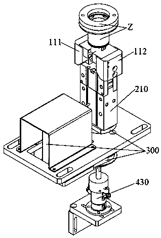
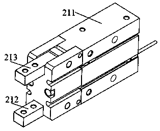
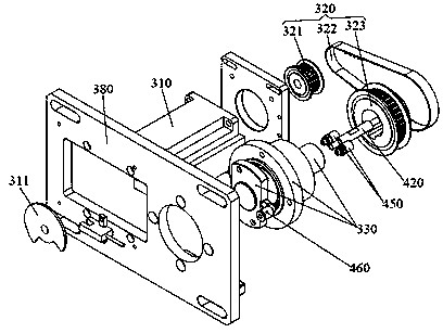
[0031] like figure 1 and Figure 10 as shown, Figure 10 is an exploded view of a preferred embodiment of the fixture clamping and rotating mechanism in the present invention, because Figure 2 to Figure 9 Each part has been numbered and illustrated separately, therefore, Figure 10 Not numbered in detail. The jig clamping and rotating mechanism provided by the present invention includes: a left clamp 111, a right clamp 112, a finger cylinder 210 and a rotating assembly 300, the left clamp 111 a...


PUM


Abstract

The invention discloses a jig clamping and rotating mechanism and a ball bulb assembling system. The jig clamping and rotating mechanism comprises a finger air cylinder, a left clamp is arranged on aleft gas claw of the finger air cylinder, and a right clamp is arranged on a right gas claw of the finger air cylinder. The finger air cylinder is connected with a rotation assembly used for driving the finger air cylinder to rotate. According to the provided jig clamping and rotating mechanism, when a jig is clamped, the finger air cylinder can be directly used for driving the left clamp and theright clamp to rotate by 90 degrees, then the included angle between the left clamp and the right clamp can be freely adjusted within 0-180 degrees, wherein the included angle can be smaller than 180degrees, provided that collisions between the clamps and a workbench are avoided; and the left clamp and the right clamp are prevented from colliding with the rotating workbench, the lifting stroke ofthe air cylinder and the clamps is omitted, and the ball bulb work efficiency is improved.

Description

technical field [0001] The invention relates to the technical field of bulb assembly equipment, in particular to a jig clamping and rotating mechanism and a bulb assembly system. Background technique [0002] The jig clamping and rotating mechanism used in the bulb assembly system can be used to clamp the screw socket and drive the semi-finished bulb bulb to rotate at a certain station to complete processes such as coating heat-dissipating glue, installing LED light boards or soldering. . [0003] The jig clamping and rotating mechanism in the prior art generally includes: a jig set through the workbench and used for clamping the screw, a jig set under the workbench and used for clamping or loosening the jig, and a jig set on the jig The cylinder below is used to drive the clamp to open and close within a certain angle, and the lifting component is arranged below the cylinder and is used to drive the cylinder and the clamp to lift up and down. [0004] The reason why the l...

Claims


Application Information

Patent Timeline
Patent Type & Authority Applications(China)
IPC IPC(8): B23P19/00
CPCB23P19/00
Inventor 张清浪
Owner SHENZHEN XUANSHUO INTELLIGENT MANUFACTURING TECHNOLOGY CO LTD
Why Eureka
Try Eureka