Mechanical arm mechanism and robot

A technology of manipulators and mounting plates, which is applied in the direction of manipulators, chucks, manufacturing tools, etc., can solve the problems that the side walls should not be too soft, too slippery, have large space requirements, and cannot be applied, so as to improve space utilization and improve satisfaction , the effect of increasing the scope of application

Pending Publication Date: 2018-12-04
GUANGDONG MIDEA INTELLIGENT ROBOTICS CO LTD
View PDF0 Cites 1 Cited by
  • Summary
  • Abstract
  • Description
  • Claims
  • Application Information

AI Technical Summary

Problems solved by technology

[0002] In related technologies, there are two types of manipulator mechanisms: the first type is to grab materials by means of top suction, and its mechanical structure part is above the material, but the mechanical structure part of this type of manipulator mechanism is above the material. The space is huge, and at the same time, placing the material also requires a huge space above the target position, which makes it unsuitable for limited space on the top of the material, and this type of manipulator mechanism also requires the top of the material to have a good shape and flatness , not applicable when the top of the material is messy or loose
The second type is to grab the material by squeezing the side wall of the material and holding the material tightly. The mechanical structure of this type of manipulator mechanism is also above the material, which also requires a large space on the top of the material and has a certain impact on the rigidity of the material side wall. Certain requirements, at least one pair of side walls should not be too soft and slippery, and the symmetrical clamping method requires sufficient space on both sides of the material, which has poor adaptability

Method used


Image

  • Mechanical arm mechanism and robot
  • Mechanical arm mechanism and robot
  • Mechanical arm mechanism and robot

Examples


Embodiment Construction

[0050] In order to be able to understand the above objectives, features and advantages of the present invention more clearly, the present invention will be further described in detail below in conjunction with the accompanying drawings and specific embodiments. It should be noted that the embodiments of the application and the features in the embodiments can be combined with each other if there is no conflict.

[0051] In the following description, many specific details are set forth in order to fully understand the present invention. However, the present invention can also be implemented in other ways different from those described here. Therefore, the protection scope of the present invention is not limited to the specific details disclosed below. Limitations of the embodiment.

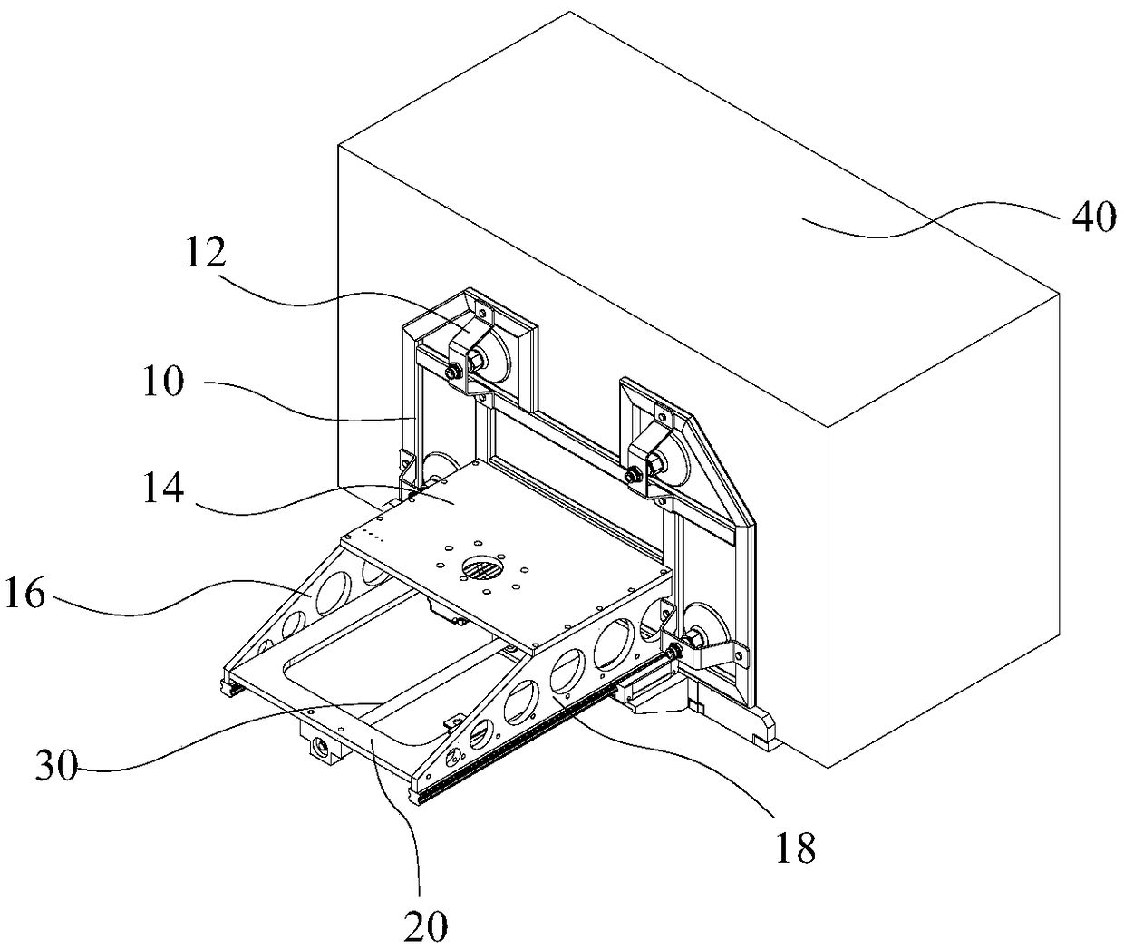
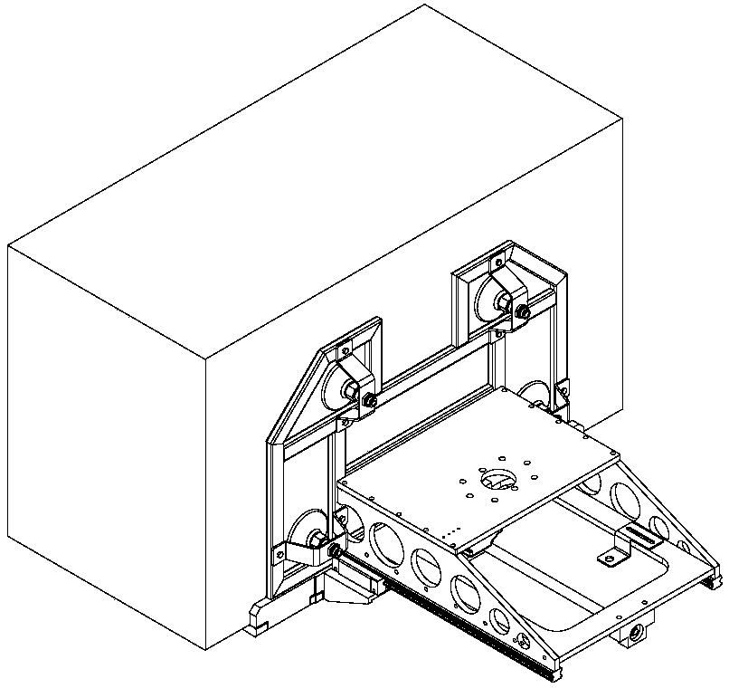
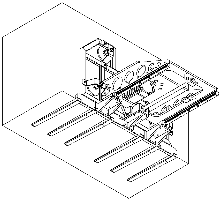
[0052] Refer below Figure 1 to Figure 18 The manipulator mechanism and robot according to some embodiments of the present invention are described.

[0053] Such as Figure 1 to Figure 7 As shown, the pre...


PUM


Abstract

The invention provides a mechanical arm mechanism and a robot. The mechanical arm mechanism comprises a main body, a sucking disc assembly, a connecting plate and a fork body assembly, wherein the sucking disc assembly is arranged on the main body, the connecting plate is arranged on the main body, and the connecting plate, the sucking disc assembly are located on the two sides of the main body respectively, and the fork body assembly is arranged on the connecting plate; and a fork body in the fork body assembly can do reciprocating motion between an initial position and a working position. According to the mechanical arm and the robot, one side face is only needed, namely a material fixing can be completed; the mechanical arm and the robot are suitable for a top cover working environmentand or a working environment with blocking on two sides above a material target position, moreover, the state of the top of the material is not required, so that the application range is greatly increased; and the fork body can be controlled to extend forwards while the material is fixed, the mode of bottom holding is adopted, so that the materials are prevented from slipping off, safety accidentsand property losses caused by the falling of the materials are avoided, the material transportation process is safer and more reliable, the fork body retracts to the initial state after carrying is completed, so that the storage space is saved.

Description

Technical field [0001] The invention relates to the technical field of logistics equipment, in particular to a manipulator mechanism and a robot. Background technique [0002] In the related art, there are two types of manipulator mechanisms: the first type is to grab materials by top suction, and the mechanical structure part is above the material, but the mechanical structure part of this type of manipulator mechanism is above the material, and the material is required to be above the material. The space is huge, and the placement of materials requires a huge space above the target position, which makes it impossible to apply when the top space of the material is limited, and this type of manipulator mechanism also requires a good shape and flatness on the top of the material , It is not applicable when the top of the material is disorderly or loose. The second type is to grab the material by squeezing the side wall of the material and holding the material tightly. The mechani...

Claims


Application Information

Patent Timeline
IPC IPC(8): B25J15/06
CPCB25J15/065B25J15/0683
Inventor 李玉光李铁芳梁耀棠
Owner GUANGDONG MIDEA INTELLIGENT ROBOTICS CO LTD
Why Eureka
Try Eureka