Automatic braking system for driverless vehicle

An unmanned vehicle and automatic braking technology, which is applied in the direction of braking safety systems, brakes, and brake components, can solve the problems of redundant structure, high cost, and low service life of anti-lock solenoid valves, so as to avoid pressure If the fluctuation is too large, the effect of ensuring driving safety and ensuring the control effect

Active Publication Date: 2018-12-04
FAW JIEFANG AUTOMOTIVE CO
View PDF10 Cites 11 Cited by
  • Summary
  • Abstract
  • Description
  • Claims
  • Application Information

AI Technical Summary

Problems solved by technology

[0004] At present, most of the existing intelligent commercial vehicles in the market are in the conventional braking system of manned driving. The existing anti-lock solenoid valve or the addition of electromagnetic relay valve and other components are used to obtain the automatic braking function of the unmanned mode. Although commercial vehicles have both manned driving and unmanned driving modes, which can be switched according to the needs of the driver, there are disadvantages in the unmanned driving mode, such as the anti-lock brake solenoid valve having a short service life and the electromagnetic relay valve having a complex structure and high cost.
For commercial vehicles used under certain working conditions, such as special-purpose work vehicles traveling on specified routes for a long time, the components such as brake pedals and brake valves in the existing system have redundant structures, which may easily cause power batteries or body parts to be damaged. The layout space of equipment and other equipment is tight, and most OEMs often sacrifice the use of space for function realization by reducing the size of the cargo box.

Method used


Image

  • Automatic braking system for driverless vehicle
  • Automatic braking system for driverless vehicle
  • Automatic braking system for driverless vehicle

Examples


Embodiment Construction

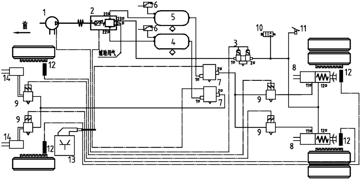
[0020] refer to figure 1 , an automatic braking system for unmanned vehicles, the braking system includes an electric air compressor 1, an electronically controlled air processing unit 2, an electronic parking memory valve 3, a front air reservoir 4, a rear air reservoir 5, Pressure sensor 6, electronically controlled brake solenoid valve 7, spring brake cylinder 8, anti-lock brake solenoid valve 9 namely ABS solenoid valve, emergency exhaust solenoid valve 10, manual exhaust valve 11, wheel speed sensor 12, brake control device 13 and front brake chamber 14.

[0021] The electric air compressor 1 provides air pressure for the entire braking system as an air source; the air outlet of the electronically controlled air compressor 1 is connected to the electronically controlled air processing unit 2 with CAN communication function. Specifically: the air outlet of the electric air compressor 1 is connected to the air inlet of the electronically controlled air processing unit 2 . ...


PUM


Abstract

The invention belongs to a pneumatic braking system and specifically relates to an automatic braking system for a driverless vehicle. The automatic braking system for the driverless vehicle comprisesan electric air compressor, an electric control air treatment unit, an electronic parking memory valve, a front air reservoir, a rear air reservoir, a pressure sensor, an electric control braking electromagnetic valve, a spring brake cylinder, an anti-lock electromagnetic valve, an emergency exhaust electromagnetic valve, a manual exhaust valve, a wheel speed sensor, a brake controller and a frontbrake air chamber. The automatic braking system for the driverless vehicle is a vehicle for a driverless operating mechanism; the vehicle has no steering wheel, braking and accelerator pedal, a transmission operator and so on; the automatic braking system for the driverless vehicle satisfies the actual demand of the control of the braking system; and according to the automatic braking system forthe driverless vehicle, automatic braking function can be realized without driver input, the structure of the system can be furthest optimized, the development cost of the system can be reduced, and the shortcomings of an existing automatic braking system are overcome.

Description

technical field [0001] The invention belongs to an air pressure braking system, in particular to an automatic braking system for an unmanned vehicle. Background technique [0002] With the continuous improvement of vehicle technology, the application of unmanned driving technology in the automotive field is becoming more and more extensive. For commercial vehicles, unmanned driving technology can not only reduce driver fatigue and improve driving safety, but also can effectively optimize the vehicle engine or motor load to achieve the effect of energy saving and emission reduction. [0003] When the driving vehicle encounters obstacles in front of it, the driver can slow down the vehicle to stop or change lanes to avoid the operation according to the road condition information; while the unmanned vehicle needs to realize the function of sensing road condition information based on the vehicle's own camera and radar, etc. And apply automatic braking and / or automatic steering ...

Claims


Application Information

Patent Timeline
Patent Type & Authority Applications(China)
IPC IPC(8): B60T13/68B60T15/04B60T17/18
CPCB60T13/683B60T15/041B60T17/18
Inventor 柳帅冷彪刘森磊邹伟
Owner FAW JIEFANG AUTOMOTIVE CO
Why Eureka
Try Eureka