Sewing machine oil box

A sewing machine and oil box technology, applied in sewing machine components, sewing equipment, textiles and papermaking, etc., can solve problems such as oil circuit and mechanism damage, equipment pollution, oil leakage, etc., to prevent oil leakage, prevent damage to equipment, The effect of adding oil is convenient

Inactive Publication Date: 2018-12-04
SUZHOU KAICHENG SEWING EQUIP
View PDF0 Cites 0 Cited by
  • Summary
  • Abstract
  • Description
  • Claims
  • Application Information

AI Technical Summary

Problems solved by technology

During the working process of household sewing machines and industrial sewing machines, a certain amount of iron filings will be generated due to the mutual friction of certain mechanisms, which may cause some iron filings to exist in some mechanisms inside the machine or in the inner cavity of the casing, and the iron filings will flow with the oil. If it flows into the bottom oil box and accumulates in the box body, some iron chips may be sucked up by the oil return pump and enter the oil supply pipeline, or be stirred up, causing damage to the oil circuit and mechanism
And the structure of the existing sewing machine oil box is very simple, just an open rectangular box body installed under the base plate, which is used to accept the oil fluid returned by the lubricating mechanism, and its position is set according to the needs of the oil circuit
During use, the head of the sewing machine often needs to be turned up for function adjustment or maintenance. When the oil box is tilted, the oil will easily leak out, contaminate the equipment and the sewing material at the same time, causing trouble
For this reason, in use, sometimes the problem is solved by installing less oil, but it causes frequent trouble of adding oil, which is extremely inconvenient. Therefore, further improvement is needed

Method used


Image

  • Sewing machine oil box
  • Sewing machine oil box
  • Sewing machine oil box

Examples


Embodiment Construction

[0017] The preferred embodiments of the present invention will be described below in conjunction with the accompanying drawings. It should be understood that the preferred embodiments described here are only used to illustrate and explain the present invention, and are not intended to limit the present invention.

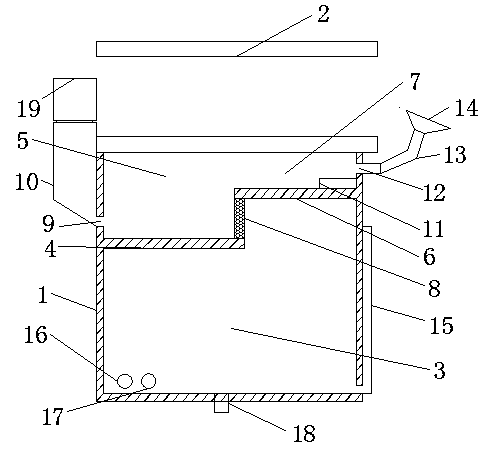
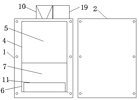
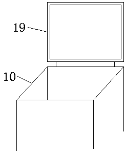
[0018] like Figure 1-Figure 3 As shown, a sewing machine oil box includes a box body 1 and a box cover 2. The box body 1 and the box cover 2 are sealed and connected by screws to prevent oil leakage when the oil box is tilted. The bottom of the inner cavity of the box body 1 A first oil chamber 3 is provided, and a support plate A4 is provided above the first oil chamber 3, and the support plate A4 is fixedly connected with the inner wall of the box body 1 to form a second oil chamber 5. The support plate A4 A support plate B6 is arranged above one side, and the support plate B6 is fixedly connected with the inner wall of the box body 1 to form a third oil chamber ...


PUM


Abstract

The invention relates to a sewing machine oil box, including a box body and a box cover. The box body and the box cover are connected in a sealed manner through screws. The bottom of an inner cavity of the box body is provided with a first oil cavity. A supporting plate A is arranged on the upper part of the first oil cavity. The supporting plate A and the inner wall of the box body are fixedly connected to form a second oil cavity. A supporting plate B is arranged on the upper part of one side of the supporting plate A. The supporting plate B and the inner wall of the box body are fixedly connected to form a third oil cavity. A filter screen is connected between the supporting plate A and the supporting plate B. One side of the box body, close to the supporting plate A, is provided with an oil filling port, and the oil filling port is above the supporting plate A. One side of the box body, close to the oil filling port, is connected with an oiling groove. The bottom of the oiling groove is inclined. The oil box is simple in structure and rational in design, and can effectively return oil and supply oil, and can effectively prevent oil from leaking out. The oil box can filter scrapiron and impurities, preventing a sewing device from being damaged when oil is supplied. The oil box can easily inject oil liquid, and use is convenient.

Description

technical field [0001] The invention relates to a sewing machine oil box, which belongs to the technical field of sewing machine equipment. Background technique [0002] A sewing machine is a machine that uses one or more sewing threads to form one or more stitches on the sewing material to interweave or sew one or more layers of sewing material. The sewing machine can sew fabrics such as cotton, hemp, silk, wool, and artificial fibers, and products such as leather, plastics, and paper, and the stitches that are sewed are not only neat and beautiful, flat and firm, but also have a fast sewing speed and are easy to use. Therefore, the sewing machine It is widely used in the sewing industry. Sewing machines are simply divided into household sewing machines and industrial sewing machines. Most of the industrial sewing machines are general-purpose sewing machines, including lockstitch sewing machines, chain sewing machines, overlock sewing machines and interlock sewing machines...

Claims


Application Information

Patent Timeline
IPC IPC(8): D05B71/00
CPCD05B71/00
Inventor 季锴
Owner SUZHOU KAICHENG SEWING EQUIP
Why Eureka
Try Eureka