Automatic testing device for work circle performance of valve for automatic water spraying fire extinguishing system

An automatic test and work cycle technology, applied in the direction of measuring devices, testing of mechanical components, testing of machine/structural components, etc., can solve the problems of many human interference factors, high labor intensity, low testing quality and efficiency, etc., to reduce The effect of human interference factors, reducing labor intensity, and improving test quality and efficiency

Active Publication Date: 2018-12-04
山东和富工程检测有限公司
View PDF9 Cites 2 Cited by
  • Summary
  • Abstract
  • Description
  • Claims
  • Application Information

AI Technical Summary

Problems solved by technology

[0002] Fire gate valves, butterfly valves, ball valves, globe valves, solenoid valves, signal valves, one-way valves, buried valves and other valves used in automatic sprinkler systems need to conduct spot checks for working cycle performance tests. The number of working cycles is 5000 times. There is no damage to all parts of the flexible closing. The working pressure, shape structure, driving mode and connection form of these valves are different. Now the performance test is mostly performed manually. There are labor intensity, human interference factors and detection quality in the test and the problem of inefficiency

Method used


Image

  • Automatic testing device for work circle performance of valve for automatic water spraying fire extinguishing system
  • Automatic testing device for work circle performance of valve for automatic water spraying fire extinguishing system
  • Automatic testing device for work circle performance of valve for automatic water spraying fire extinguishing system

Examples


Embodiment Construction

[0021] The present invention will be described in further detail below in conjunction with the accompanying drawings and specific embodiments, to help those skilled in the art have a more complete, accurate and in-depth understanding of the inventive concept and technical solutions of the present invention. The protection scope of the present invention includes but is not limited to In the following examples, without departing from the spirit and scope of the present application, any modifications made to the details and forms of the technical solutions of the present invention fall within the protection scope of the present invention.

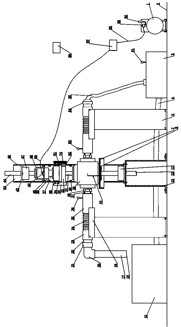
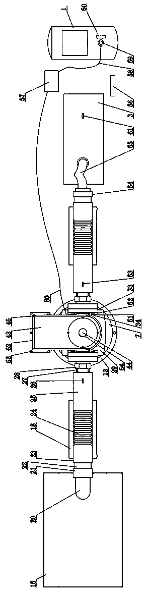
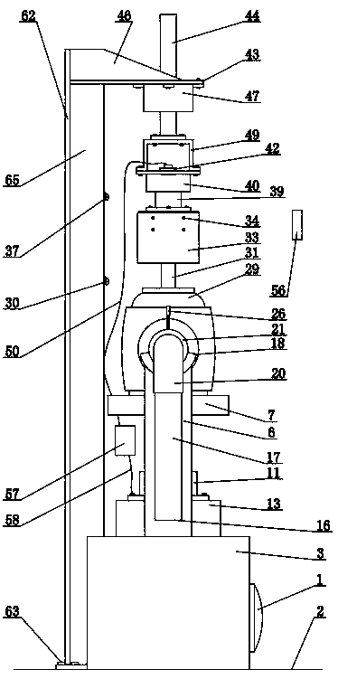
[0022] attached figure 1 It is a specific embodiment of the present invention. This embodiment includes an air pump 1 , a water booster pump 3 , a water reservoir 15 and a valve sample 29 . Air pump 1, water booster pump 3, reservoir 15 are placed on the ground, and the water inlet pipe 4 of water booster pump 3 is connected with reservoir 15...


PUM


Abstract

The invention discloses an automatic testing device for work cycle performance of a valve for a water spraying fire extinguishing system. The device comprises an air pump, a water boosting pump, a reservoir and a valve sample. The water boosting pump is connected with the reservoir. The right side of the valve sample is connected with the water boosting pump, and the left side is connected with awater outlet pipe. Water falls into the reservoir from the water outlet of the water outlet pipe. The top end of the valve sample is connected with a valve sample cyclic action control device. The valve sample cyclic action control device is connected with a hollow shaft torque measuring motor. The hollow shaft torque measuring motor is fixed to the lower end of a vertical telescopic shaft I. A telescopic shaft motor I is fixed to a horizontal board. The horizontal board is welded to a frame. The frame is fixed on ground. An air pump is connected with a pneumoelectric rotatable joint. The pneumoelectric rotatable joint is connected with a valve sample cyclic action control device. The automatic testing device can automatically determine whether opening or closing of the valve in an experiment is flexible and whether component damage occurs, reducing artificial interference factors, improving testing automation, improving testing quality and efficiency.

Description

technical field [0001] The invention belongs to the technical field of fire protection product detection, and in particular relates to an automatic test device for the working cycle performance of a valve used in an automatic sprinkler system. Background technique [0002] Fire gate valves, butterfly valves, ball valves, globe valves, solenoid valves, signal valves, one-way valves, buried valves and other valves used in automatic sprinkler systems need to conduct spot checks for working cycle performance tests. The number of working cycles is 5000 times. There is no damage to all parts of the flexible closing. The working pressure, shape structure, driving mode and connection form of these valves are different. Now the performance test is mostly performed manually. There are labor intensity, human interference factors and detection quality in the test and low efficiency issues. Contents of the invention [0003] In order to make up for the deficiencies of the prior art, t...

Claims


Application Information

Patent Timeline
Patent Type & Authority Applications(China)
IPC IPC(8): G01M13/00
CPCG01M13/00Y02A40/28
Inventor 朱亚州赵叶蕾张根源刘传铭王庭
Owner 山东和富工程检测有限公司
Why Eureka
Try Eureka