Self-propelled soil turning device for greenhouse planting

A self-propelled, support rod technology, applied to agricultural machinery and tools, agriculture, shovels, etc., can solve the problems that the tiller is difficult to turn around, damage the growth of crops, affect the germination rate, etc., achieve simple structure, increase germination rate, The effect of enhancing the effect

Active Publication Date: 2021-01-22
繁昌县小时候生态农业科技有限公司
View PDF4 Cites 0 Cited by
  • Summary
  • Abstract
  • Description
  • Claims
  • Application Information

AI Technical Summary

Problems solved by technology

[0002] At present, the planting in the agricultural greenhouses is a strip-shaped soil slope device, and a walking passage is formed between the two soil slopes, so that the edge planters can walk around and perform operations on the planting of agricultural products, such as turning the soil, applying pesticides and weeding, etc. Turning the soil is a relatively heavy operation in planting, and turning the soil is to increase the air permeability in the soil, avoid better air tightness, affect the respiration of the seeds and affect the germination rate, and the general way of turning the soil is to use a shovel to turn the soil manually Soil, the labor force is relatively strong, and the efficiency is extremely low, and the tiller is generally large, walking in the greenhouse and destroying the growth of the crops on the other side, and it is difficult for the tiller to turn around in the greenhouse, which is more troublesome

Method used


Image

  • Self-propelled soil turning device for greenhouse planting
  • Self-propelled soil turning device for greenhouse planting
  • Self-propelled soil turning device for greenhouse planting

Examples


Embodiment Construction

[0017] The following will clearly and completely describe the technical solutions in the embodiments of the present invention with reference to the accompanying drawings in the embodiments of the present invention. Obviously, the described embodiments are only some, not all, embodiments of the present invention. Based on the embodiments of the present invention, all other embodiments obtained by persons of ordinary skill in the art without making creative efforts belong to the protection scope of the present invention.

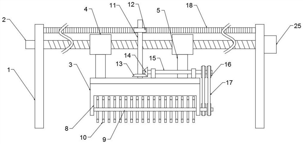
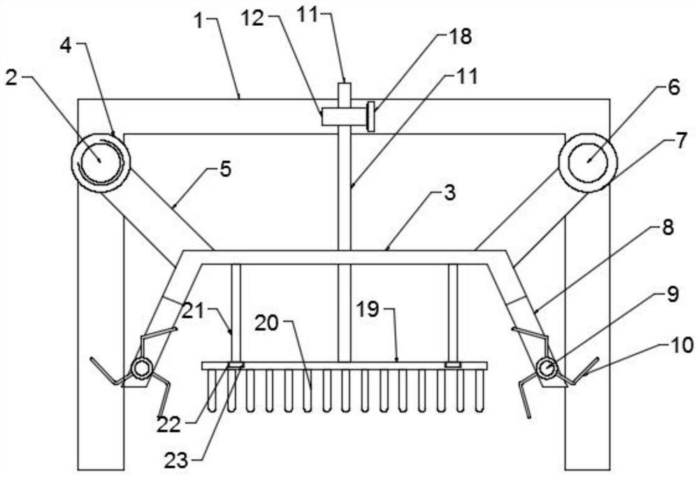
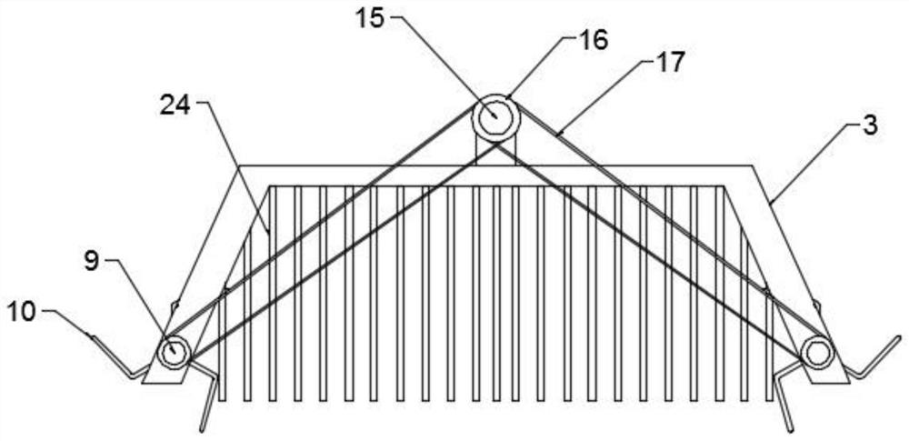
[0018] see Figure 1~3 , in an embodiment of the present invention, a self-propelled tillage device for greenhouse planting includes two support rod frames 1, and a horizontal screw 2 and a limiting slide rod 6 are arranged between the upper ends of the two support rod frames 1, and the horizontal screw rod The two ends of 2 are respectively connected with two support rod frames 1 in rotation, and one end of the horizontal wire rod 2 is connected with the driv...


PUM


Abstract

The invention discloses a self-propelled soil turning device for greenhouse planting. The self-propelled soil turning device comprises two supporting rod frames; a transverse screw rod and a limitingsliding rod are arranged between the upper ends of the two supporting rod frames; two ends of the transverse screw rod are respectively and rotationally connected with the two supporting rod frames; two side walls of a mounting frame body are respectively provided with end openings; a poking transverse shaft is arranged inside the end openings; a plurality of poking rods are arranged and distributed on the poking transverse shaft; a rotating vertical shaft which is rotationally connected with the mounting frame body vertically penetrates through the middle of the mounting frame body; a rotating gear is arranged at the top end of the rotating vertical shaft; a transverse rack is fixedly connected between the two supporting rod frames; the rotating gear is meshed with the transverse rack; two ends of a transmission transverse shaft are installed on the top wall of the mounting frame body through supporting; a driven bevel gear is arranged at one end of the transmission transverse shaft;and the driven bevel gear is meshed with a driving bevel gear arranged on the rotating vertical shaft. The device is simple in structure, the soil turning and crushing effect is obvious, and air permeability of soil is improved. In addition, the device can move by itself, so that manual pushing is avoided, labor consumption is reduced, and practicability is high.

Description

technical field [0001] The invention relates to the technical field of agricultural planting machinery, in particular to a self-propelled soil turning device for greenhouse planting. Background technique [0002] At present, the planting in the agricultural greenhouses is a strip-shaped soil slope device, and a walking passage is formed between the two soil slopes, so that the edge planters can walk around and perform operations on the planting of agricultural products, such as turning the soil, applying pesticides and weeding, etc. Turning the soil is a relatively heavy operation in planting, and turning the soil is to increase the air permeability in the soil, avoid better air tightness, affect the respiration of the seeds and affect the germination rate, and the general way of turning the soil is to use a shovel to turn the soil manually Soil, the labor force is relatively strong, and the efficiency is extremely low, and the tiller is generally large, and it will damage t...

Claims


Application Information

Patent Timeline
Patent Type & Authority Patents(China)
IPC IPC(8): A01B49/02
CPCA01B49/022
Inventor 马冬梅
Owner 繁昌县小时候生态农业科技有限公司
Why Eureka
Try Eureka