Coating stirring device for construction site

A construction site, stirring device technology, applied in mixers with rotating stirring devices, transportation and packaging, dissolving, etc., can solve the problems of poor stirring effect, achieve the effect of increasing mixing effect, novel design, and improving mixing efficiency

Pending Publication Date: 2018-12-07
ANHUI YONSENT PHARMA
View PDF8 Cites 12 Cited by
  • Summary
  • Abstract
  • Description
  • Claims
  • Application Information

AI Technical Summary

Problems solved by technology

This uniform stirring device for architectural paint has the first stirring blade and the second stirring blade fixedly connected to one side of the stirring rod, and the first stirring blade is placed horizontally and the second stirring blade is vertically placed to achieve uniform stirring of the paint. Eff

Method used


Image

  • Coating stirring device for construction site
  • Coating stirring device for construction site
  • Coating stirring device for construction site

Examples


Embodiment 1

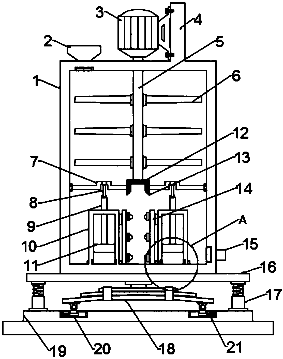
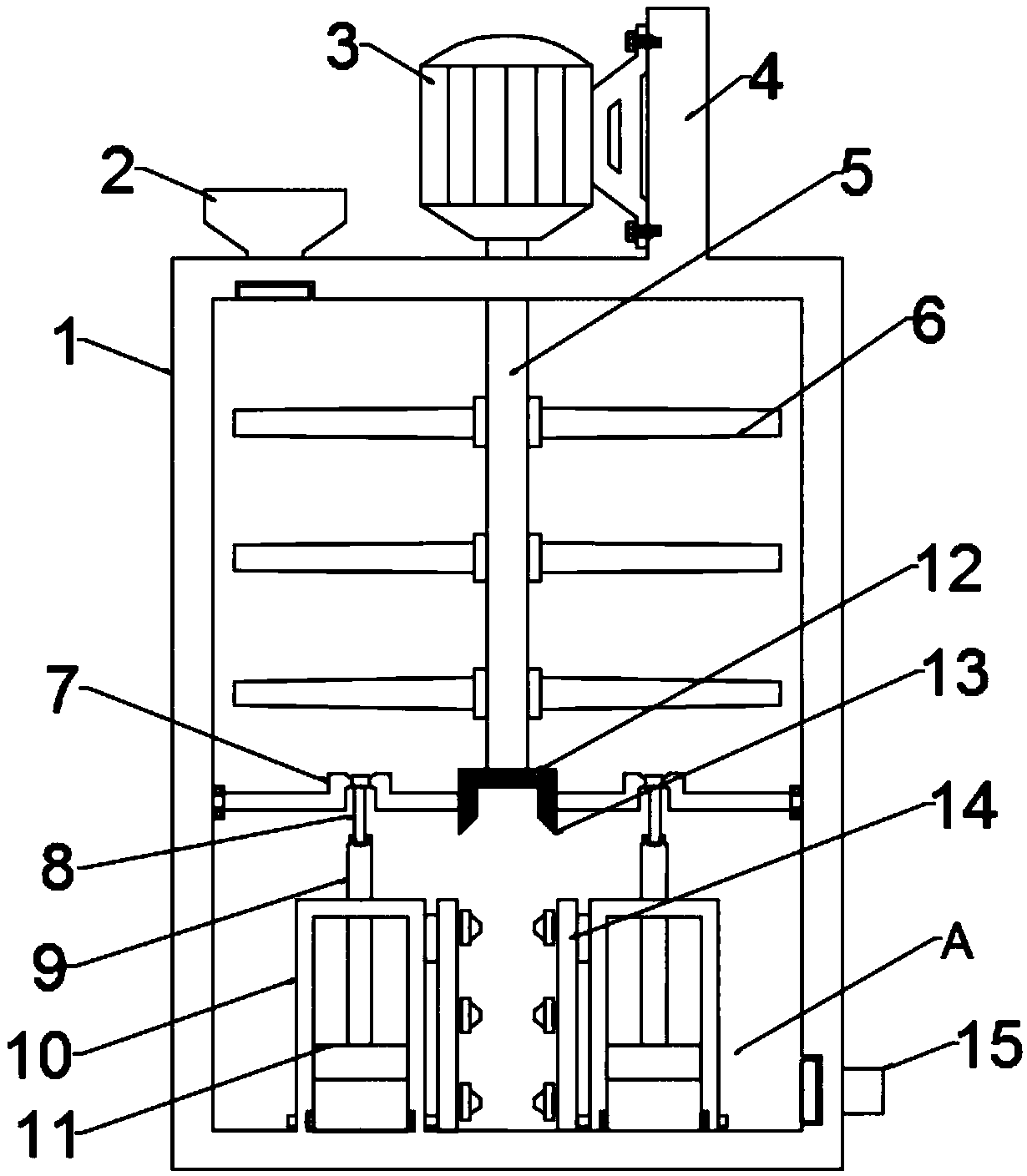
[0023] see figure 2 and 4 , in an embodiment of the present invention, a paint stirring device for a construction site includes a stirring chamber 1, a motor 3 and a pumping mechanism; the inner lower end of the stirring chamber 1 is symmetrically installed with a pumping mechanism, and the pumping mechanism includes a crankshaft 7 and a connecting rod 8 , push rod 9, piston cylinder 10, piston 11 and nozzle pipe 14, nozzle pipe 14 is provided with two symmetrically and is positioned at the inner side of two piston cylinders 10, piston cylinder 10 is communicated with nozzle pipe 14 by connecting pipe 22, nozzle pipe 14 A spray head is arranged on the piston cylinder 10, and a feeding pipe 23 is arranged at a position opposite to the connecting pipe 22 on the piston cylinder 10. A one-way valve is arranged in the connecting pipe 22 and the feeding pipe 23, and the mixture in the stirring chamber 1 Enter the piston cylinder 10 from the feed pipe 23, then enter the spray pipe ...

Embodiment 2

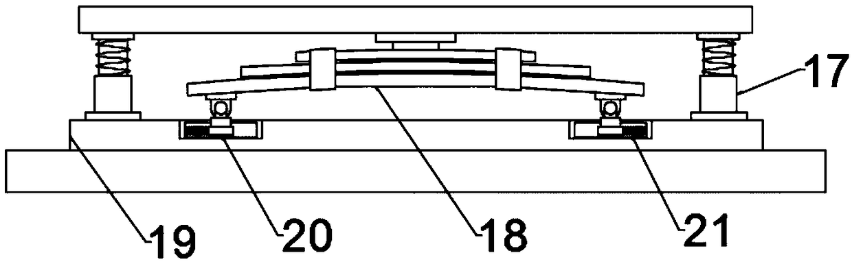
[0028] see figure 1 , 3 And 4, the difference between embodiment two and embodiment one is that the lower end of the stirring chamber 1 is equipped with a shock absorbing mechanism, which includes a fixed plate 16, a telescopic rod 17, a leaf spring 18, a bottom plate 19 and a slider 20, and the fixed The plate 16 is fixedly connected with the lower end of the stirring chamber 1, and the lower end of the fixed plate 16 is connected with the bottom plate 19 through a symmetrically arranged telescopic rod 17, the outer end of the telescopic rod 17 is provided with a spring, and the leaf spring 18 is arranged on two described On the inner side of the telescopic rod 17, the upper end of the leaf spring 18 is fixedly connected to the lower end of the fixed plate 16, and both sides of the lower end of the leaf spring 18 are hinged with symmetrically arranged sliders 20, and the slider 20 is slidably connected to the chute arranged on the bottom plate 19 Inside, the outer end of the...


PUM


Abstract

The invention discloses a coating stirring device for a construction site. The coating stirring device comprises a stirring cavity, a motor and pumping mechanisms, wherein the pumping mechanisms are symmetrically mounted at the lower end of the inner side of the stirring cavity and comprise crank shafts, connecting rods, pushing rods, piston cylinders, pistons and spray pipes, the spray pipes aresymmetrically located on the inner sides of two piston cylinders, the piston cylinders are communicated with spray pipes through communication pipes, pistons are arranged in the piston cylinders, andthe upper ends of the pistons are fixedly connected with one ends of the push rods. The coating stirring device is novel in design; when the arranged crank shafts rotate, the pistons are driven to doa reciprocating up-down motion in the piston cylinders under the action of the connecting rods and the push rods, so that a pumping process is realized; a mixture in the stirring cavity enters the piston cylinders through feeding pipes, enters the spray pipes through the communication pipes and is sprayed out from the spray heads, and a coating sprayed out from the oppositely arranged spray pipesis impacted to be dispersed outwards, so that the mixing efficiency of the coating is improved, and the mixing effect is increased.

Description

technical field [0001] The invention relates to a relatively large scope, in particular to a paint stirring device for a construction site. Background technique [0002] The paint mixer crushes, disperses, emulsifies, and mixes the paint. Through the new high-efficiency stirring equipment with high-speed operation of the upper and lower teeth of the dispersing plate, the material is strongly sheared, impacted, crushed, and dispersed at a high speed to achieve rapid mixing, dissolution, Scattered and refined functions. It is an efficient equipment for stirring, dispersing and dissolving solids such as coatings. [0003] CN207385309U in the existing patent discloses a stirring device for evenly stirring architectural paint, including a base, the top of the base is fixedly connected with the bottom of the support plate, and one side of the support plate is fixedly connected with a slide rail, and the slide rail Slidingly connected with the slider, one side of the slide rail i...

Claims


Application Information

Patent Timeline
IPC IPC(8): B01F7/18B01F5/02
CPCB01F25/21B01F27/90B01F2101/30
Inventor 夏运喜殷毡毡刘莎莎
Owner ANHUI YONSENT PHARMA
Why Eureka
Try Eureka