

Compression die
A technology of pressing dies and dies, applied in the direction of metal extrusion dies, etc., can solve the problems of inability to meet the shape requirements of components, difficulty in unloading, folding, etc.
- Summary
- Abstract
- Description
- Claims
- Application Information
AI Technical Summary
Problems solved by technology
Method used
Image

Examples
Embodiment Construction
[0029] Embodiments of the present invention will be described below in conjunction with the accompanying drawings.
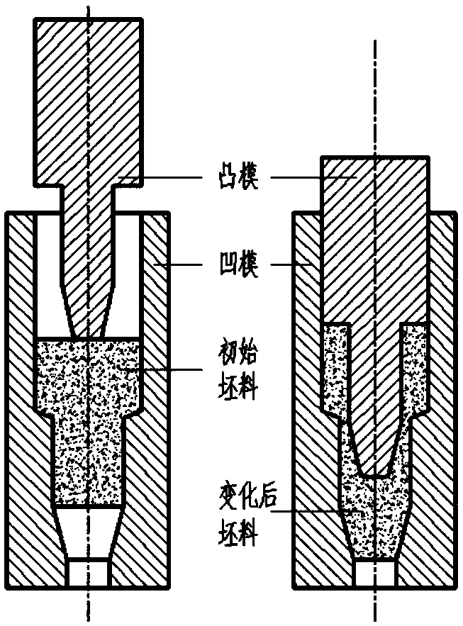
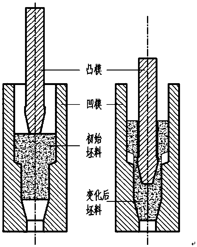
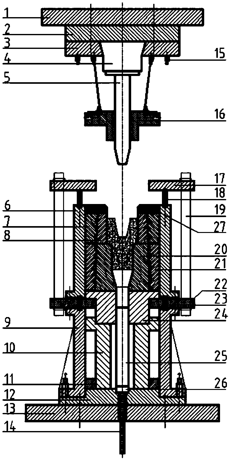
[0030] Such as Figure 2a In the initial blank, the outer diameter of the big end is Φ384mm, the outer diameter of the big end is Φ256mm, the diameter of the inner hole is Φ184mm, and the total height of the blank is 629mm. The deformation resistance F of the punch 216 during the pressing process 实测 is 1100 tons, the allowable tensile and compressive stress [P 面 ] is 120MPa, then pass It is calculated that the total contact area between the upper pressure ring 17 and the three symmetrically distributed rolling fan rings 28 is at least 91666.67mm 2 , then the contact area with a single rolling sector ring 28 is at least 30555.56mm 2 . For this reason, the inner diameter of the rolling fan ring 28 is designed to be Φ640mm and the outer diameter is Φ860mm, so its single contact area is 43196.956mm 2 ,Meet the design requirements.
[0031] Simultaneously des...
PUM
| Property | Measurement | Unit |
|---|---|---|
| area | aaaaa | aaaaa |
| diameter | aaaaa | aaaaa |
Abstract
Description
Claims
Application Information