
Axial differential-pressure heat-state internal-pressure forming method of special-shaped variable-cross-section pipe fitting

A technology for deformation and pipe fittings, which is applied in the field of axial differential pressure hot-state internal pressure forming of special-shaped and variable-section pipe fittings. The effect of controllable distribution, coordinated deformation and wide application range

Active Publication Date: 2018-12-07
HARBIN INST OF TECH
View PDF6 Cites 7 Cited by
  • Summary
  • Abstract
  • Description
  • Claims
  • Application Information

AI Technical Summary

Problems solved by technology

[0011] The present invention aims to solve the problem that the pressure of the pipe fittings cannot be controlled in different regions during the hot internal high-pressure forming method of the existing special-shaped variable cross-section pipe fittings, resulting in the inability to effectively and reasonably control the deformation and wall thickness distribution of each region, and further proposes A hot-state internal pressure forming method of axial differential pressure for special-shaped variable-section pipe fittings

Method used


Image

  • Axial differential-pressure heat-state internal-pressure forming method of special-shaped variable-cross-section pipe fitting
  • Axial differential-pressure heat-state internal-pressure forming method of special-shaped variable-cross-section pipe fitting
  • Axial differential-pressure heat-state internal-pressure forming method of special-shaped variable-cross-section pipe fitting

Examples


specific Embodiment approach 1

[0039] Specific implementation mode one: see Figure 5 Note that the axial differential pressure thermal internal pressure forming method of a special-shaped cross-section pipe fitting in this embodiment is realized according to the following steps:

[0040] Step 1, heating the mold 2 to 150-500°C;

[0041] Step 2, put the original tube blank 3 into the hot mold, close the mold 2, and apply a certain clamping force;

[0042] Step 3, the punch 4 moves to contact and seal the tube blank 3, and then fills the inside of the tube blank 3 with a hot fluid medium 6 at 150-500°C through the internal pipeline 5;

[0043] Step 4. When the mold 2, the tube blank 3, and the fluid medium 6 reach the target temperature, start the supercharger that controls the internal pressure of the tube blank 3, and establish a certain initial pressure inside the tube blank 3. Under the action of this pressure, the tube blank 3 The transition area 7 between the axial areas of the billet 3 is closely at...

specific Embodiment approach 2

[0047] Specific implementation mode two: see Image 6 Explain that the difference between this embodiment and the specific embodiment 1 is that in the axial differential pressure hot state internal pressure forming method for special-shaped variable cross-section pipe fittings in this embodiment, there is no transition section on the final required pipe fitting that can be first bonded to the mold , so it is necessary to add a device on the mold or the tube blank that can separate the two areas with different cross-sections, so that there is a transition area 7 between the areas of the tube blank 3. In this embodiment, the mold at the junction of the two adjacent areas The movable insert 9 is set to be movable, corresponding to the transition area 7 of the tube blank 3. In step 4, the movable insert 9 is driven by the external force F to move to the inside of the cavity to form a shape with a small cross-sectional area. Under the action of the initial pressure, the tube blank ...

specific Embodiment approach 3

[0049] Specific implementation mode three: see Figure 7 and Figure 8 Note, the difference between this embodiment and the specific embodiment 1 or 2 is: a hot internal pressure forming method using axial differential pressure in this embodiment, in step 2, the original metal tube blank is 6061 aluminum alloy seamless The tube blank or AZ31 magnesium alloy tube blank has a wall thickness of 1.0-5.0mm, an outer diameter of 20-60mm, and a non-circular cross-sectional shape such as trapezoid or rectangle.

[0050] As a preference, the original tube blank 3 can be prepared by filling the inside of the circular tube blank with 2-10 MPa gas or liquid and then closing the molds.

[0051] In this embodiment, according to the different structural features of the final pipe fittings, different initial shapes of the pipe blanks are used, which can effectively control the wall thickness distribution of the formed special-shaped variable cross-section pipe fittings and obtain higher shap...


PUM


Abstract

The invention relates to an axial differential-pressure heat-state internal-pressure forming method of a special-shaped variable-cross-section pipe fitting, and relates to a forming method of the pipefitting. In order to solve the problems that during the process of an existing heat-state internal-pressure forming method of the special-shaped variable-cross-section pipe fitting, the pressure on the pipe fitting cannot be controlled in a zoning way, so that the deformation of zones and the wall thickness distribution cannot be effectively and reasonably controlled, the method comprises the following steps of (1) heating a mold; (2) placing an original pipe blank into the heat-state mold; (3) moving a punch to contact the pipe blank, sealing, and then filling a heat-state fluid medium intothe pipe blank through an internal pipeline; (4) starting a supercharger for controlling the internal pressure of the pipe blank so as to separate and seal the zones in the axial direction; (5) starting a supercharger for controlling the external pressure of the pipe blank, and filling pressure media with different sizes into the axial zones of the pipe blank; and (6) controlling the internal pressure and the external pressure of the pipe blank, enabling the pipe blank to deform, and obtaining the required special-shaped variable-cross-section pipe fitting. The axial differential-pressure heat-state internal-pressure forming method of the special-shaped variable-cross-section pipe fitting provided by the invention is used for forming the special-shaped variable-cross-section pipe fitting.

Description

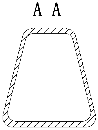
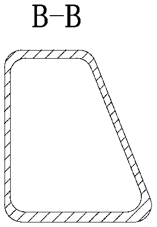
technical field [0001] The invention relates to a forming method of a pipe fitting, in particular to an axial differential pressure hot-state internal pressure forming method of a special-shaped variable cross-section pipe fitting. Background technique [0002] In the fields of automobiles, high-speed rail, aerospace and other fields, lightweight is one of the main goals pursued. In order to meet the lightweight requirements, a large number of special-shaped variable-section pipe fittings (such as Figure 1-Figure 4 shown), one method of producing such parts is the internal hydroforming technique. [0003] Internal high pressure forming uses the pipe as the blank, and the pipe is pressed into the mold cavity by applying high-pressure liquid and axial feeding inside the pipe to form it into a workpiece of the desired shape. In the design of the hollow variable cross-section structure of internal high pressure forming, in order to achieve weight reduction and adapt to differe...

Claims


Application Information

Patent Timeline
Patent Type & Authority Applications(China)
IPC IPC(8): B21D26/033B21D26/047
CPCB21D26/033B21D26/047
Inventor 何祝斌赵立栋苑世剑
Owner HARBIN INST OF TECH
Learn More