Steel pipe stamping and punching machine

A technology for punching machines and steel pipes, which is applied in the field of steel pipe stamping devices, can solve the problems of affecting the punching efficiency and pass rate, the difficulty of controlling the punching distance, and the inconvenience of adjusting the punching machine, so as to improve the punching efficiency and ensure the efficiency And qualified rate, the effect of high degree of automation

Pending Publication Date: 2018-12-07
HAIYAN HUITONG INTELLIGENT FURNITURE CO LTD
View PDF10 Cites 3 Cited by
  • Summary
  • Abstract
  • Description
  • Claims
  • Application Information

AI Technical Summary

Problems solved by technology

[0002] Steel pipes are widely used in our daily life. The uses of steel pipes are very extensive. During the use of steel pipes, it is often necessary to punch holes on the surface of steel pipes to meet the processing and use of steel pipes. There are many types of pipe punching machines available. , some pipe punching machines can punch pipes separately, and some pipe punching machines can drill holes on the outer surface of the pipe at the same time. The existing pipe punching machines generally use a fixed drill to move holes. In the process of drilling, it is necessary to manually push the pipe to the fixed drill bit to punch the pipe; on the one hand, it requires a lot of manpower and the work efficiency is low; on the other hand, it is The current punching machine is not easy to adjust, making it difficult to control the punching distance, which seriously affects the efficiency and pass rate of punching

Method used


Image

  • Steel pipe stamping and punching machine
  • Steel pipe stamping and punching machine
  • Steel pipe stamping and punching machine

Examples


Embodiment

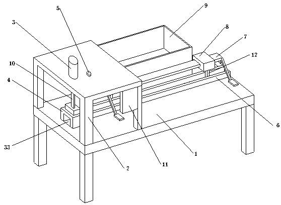
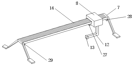
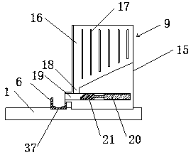
[0029] Embodiment: a kind of steel pipe stamping punching machine, as attached Figure 1-8As shown, it includes a workbench 1, a fixed frame 2 is arranged above the workbench 1, a first cylinder 3 vertically downward is embedded on the fixed frame 2, and a positioning frame 4 is arranged below the first cylinder 3; The extended end of a cylinder 3 is provided with a stamping plate 10, and the bottom of the stamping plate 10 is provided with a punching tool 22; U-shaped guide plate 6 is arranged, and the top of U-shaped guide plate 6 is provided with sliding frame 7, and sliding frame 7 is provided with sliding mechanism 8, and the bottom of sliding mechanism 8 is connected with the push rod 12 that stretches into U-shaped guide plate 6 inner cavity, pushes The end of the rod 12 is connected with a push block 13; one side of the U-shaped guide plate 6 is provided with a pipe delivery device 9; the fixed frame 2 is embedded with a laser displacement sensor 5 above the U-shaped g...


PUM


Abstract

The invention discloses a steel pipe stamping and punching machine. The steel pipe stamping and punching machine comprises a workbench. A fixed frame is arranged on the upper portion of the workbench.A first cylinder arranged vertically downwards is inlaid in the fixed frame. A locating frame is arranged below the first cylinder. The extension end of the first cylinder is provided with a stampingplate. The bottom of the stamping plate is provided with a punching tool. The stamping plate extends into an inner cavity of the locating frame. One side of the locating frame is provided with a U-shaped guide plate. A sliding frame is erected above the U-shaped guide plate. The sliding frame is provided with a sliding mechanism. The bottom of the sliding mechanism is connected with a push rod extending into an inner cavity of the U-shaped guide plate. The end of the push rod is connected with a push block. A pipe feeding device is arranged on one side of the U-shaped guide plate. A laser displacement sensor is inlaid in the position, located above the U-shaped guide plate, of the fixed frame. The steel pipe stamping and punching machine has the advantages of being high in machining efficiency and automation degree, facilitating control and adjustment on the punching distance, saving a great deal of labor force and ensuring the punching efficiency and the qualified rate.

Description

technical field [0001] The invention relates to a steel pipe stamping device, in particular to a steel pipe stamping and punching machine. Background technique [0002] Steel pipes are widely used in our daily life. The uses of steel pipes are very extensive. During the use of steel pipes, it is often necessary to punch holes on the surface of steel pipes to meet the processing and use of steel pipes. There are many types of pipe punching machines available. , some pipe punching machines can punch pipes separately, and some pipe punching machines can punch holes on the outer surface of the pipe at the same time. The existing pipe punching machines generally use a fixed drill to move holes. In the process of punching, it is necessary to manually push the pipe to the fixed drill bit to punch the pipe; on the one hand, it needs a lot of manpower, and the work efficiency is low; on the other hand, it is The current punching machine is not easy to adjust, which makes it difficul...

Claims


Application Information

Patent Timeline
Patent Type & Authority Applications(China)
IPC IPC(8): B21D28/28B21D43/00B21C51/00
CPCB21C51/00B21D28/28B21D43/003B21D43/006
Inventor 陈志峰陈建明杨会良
Owner HAIYAN HUITONG INTELLIGENT FURNITURE CO LTD
Why Eureka
Try Eureka