Hydraulic casting equipment with defoaming function

A casting equipment and defoaming technology, which is applied in the field of hydraulic casting equipment with defoaming function, can solve the problems of incomplete molding of castings, no air bubbles discharged, and bubbles in castings, so as to improve practicability and reliability, and improve defoaming effect, the effect of reducing the amount of air bubbles

Inactive Publication Date: 2018-12-07
SHENZHEN LEILING GUANGTONG TECH DEV CO LTD
View PDF8 Cites 6 Cited by
  • Summary
  • Abstract
  • Description
  • Claims
  • Application Information

AI Technical Summary

Problems solved by technology

[0003] However, the existing hydraulic casting equipment still has some shortcomings in the actual use process. For example, when the casting equipment is in use, the molten metal in the cavity may not completely fill the cavity, and there are gaps in the corners of the cavity. In addition, the molten metal may not completely fill the cavity. There may still be some bubbles in the liquid that have not been discharged, which will lead to incomplete molding of the casting, bubbles appear inside the casting, and affect the production quality of the casting. In addition, most of the control panels on the existing casting equipment are exposed to the outside, and the control panels are easy to Damaged, and external stains are easy to blur the control screen, affecting people's use, these problems have greatly reduced the practicability and reliability of the existing hydraulic casting equipment

Method used


Image

  • Hydraulic casting equipment with defoaming function
  • Hydraulic casting equipment with defoaming function
  • Hydraulic casting equipment with defoaming function

Examples


Embodiment Construction

[0026] The present invention will now be described in further detail with reference to the drawings. These drawings are all simplified schematic diagrams, which merely illustrate the basic structure of the present invention in a schematic manner, so they only show the structures related to the present invention.

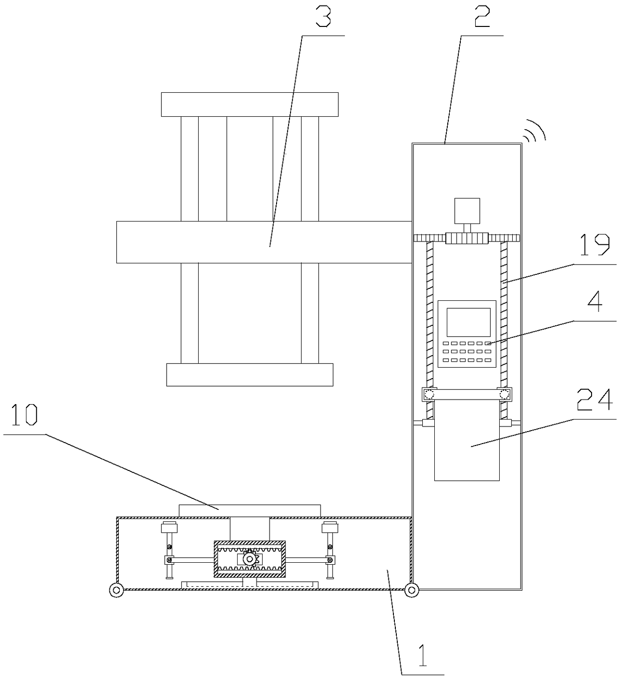
[0027] Such as figure 1 As shown, a hydraulic casting equipment with a defoaming function includes a base 1, a pillar 2, a hydraulic device 3, and a control panel 4. It also includes a defoaming mechanism and a protection mechanism, and the defoaming mechanism is arranged inside the base 1;

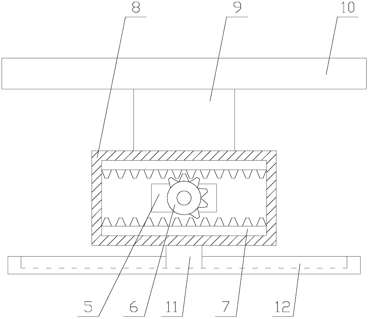
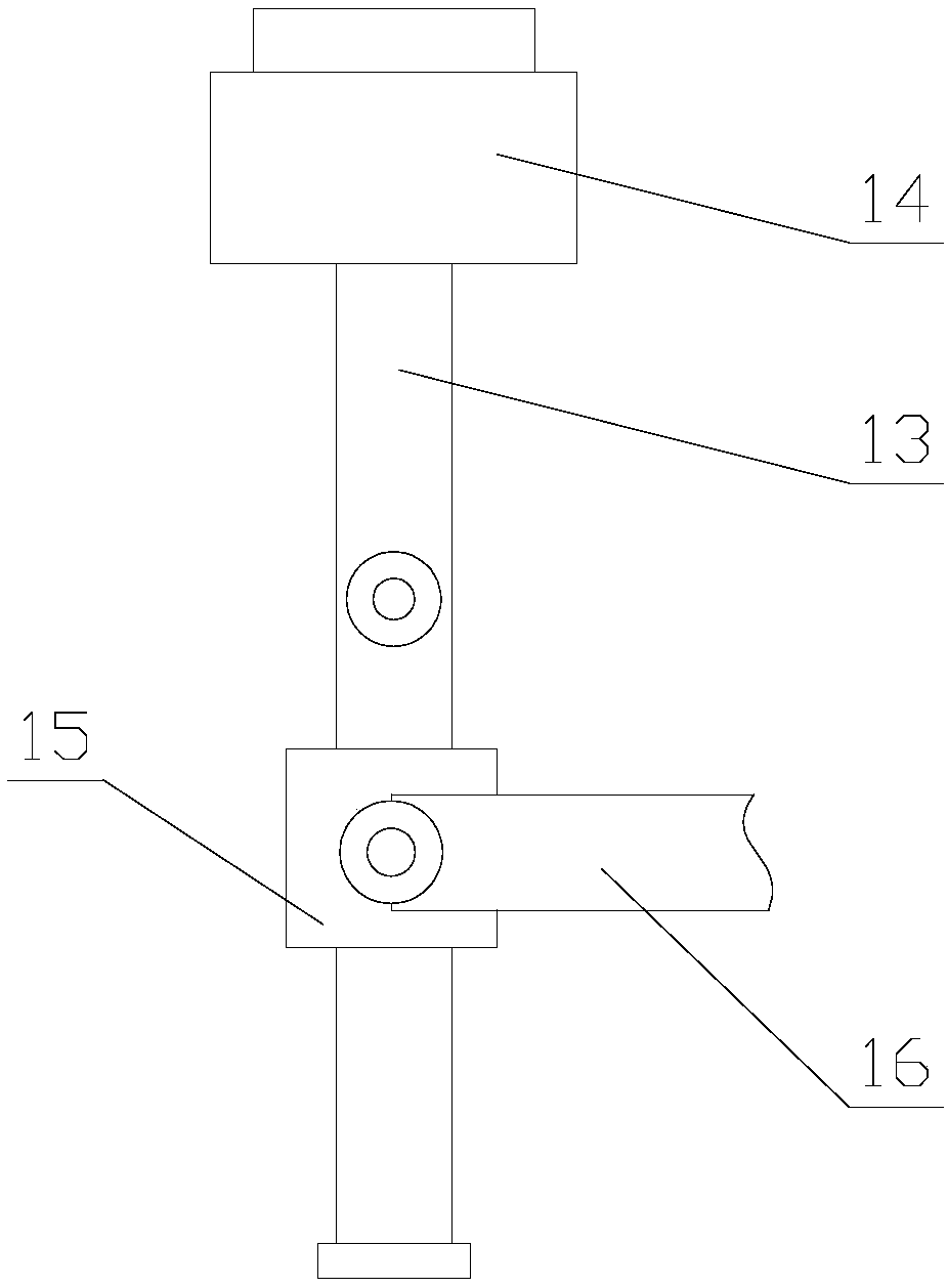
[0028] Through the defoaming mechanism, the pallet 10 can drive the mold to shake, and the ultrasonic transmitter 14 can aim at the mold to swing and emit ultrasonic defoaming. Compared with the existing hydraulic casting equipment, the corners of the mold cavity are filled and the mold cavity is reduced. There are gaps and bubbles at the corners of the metal. Ultrasonic waves can cr...


PUM


Abstract

The invention relates to hydraulic casting equipment with a defoaming function. The hydraulic casting equipment comprises a base, a supporting column, a hydraulic device and a control screen, and further comprises a defoaming mechanism and a protection mechanism, wherein the defoaming mechanism comprises a shaking assembly and an auxiliary assembly, the shaking assembly comprises a first motor, ahalf gear, a rack, a moving frame, a connecting block and a supporting plate, the auxiliary assembly comprises two swing units, the protection mechanism comprises a second motor, a first gear, a lifting plate, a baffle and two control assemblies. According to the hydraulic casting equipment with the defoaming function, through the defoaming mechanism, the supporting plate can drive a casting moldto shake, an ultrasonic wave emitter can be aligned with the casting mold to swing and emit ultrasonic waves for defoaming, so that the content of bubbles in the formed casting is reduced, the production quality of the casting is improved, a control screen can be protected through the protection mechanism, and the practicability and the reliability of the hydraulic casting equipment are greatly improved.

Description

Technical field [0001] The invention relates to the field of hydraulic casting equipment, in particular to a hydraulic casting equipment with a defoaming function. Background technique [0002] Strictly speaking, casting machinery equipment is a machine that uses this technology to smelt metal into a liquid that meets certain requirements and pour it into a casting mold. After cooling, solidification, and cleaning, castings with predetermined shapes, sizes and properties are obtained. On the other hand, the mechanical equipment related to casting can also be classified as casting equipment. [0003] However, the existing hydraulic casting equipment still has some shortcomings in the actual use process. For example, when the casting equipment is in use, the molten metal in the mold cavity may not completely fill the mold cavity, and there are gaps in the corners of the mold cavity. In addition, the molten metal There may be some bubbles in the liquid that have not been discharged, ...

Claims


Application Information

Patent Timeline
Patent Type & Authority Applications(China)
IPC IPC(8): B22D27/08B22D27/20
CPCB22D27/08B22D27/20
Inventor 陈科
Owner SHENZHEN LEILING GUANGTONG TECH DEV CO LTD
Why Eureka
Try Eureka