Eureka AIR delivers breakthrough ideas for toughest innovation challenges, trusted by R&D personnel around the world.

Automatic drilling tapping machine and working method thereof

A technology of tapping machine and drilling rig, which is applied to other manufacturing equipment/tools, manufacturing tools, metal processing equipment, etc., to achieve the effects of ensuring smoothness, liberating manpower, and reducing labor costs

Pending Publication Date: 2018-12-07
卓弢机器人盐城有限公司
View PDF13 Cites 2 Cited by
  • Summary
  • Abstract
  • Description
  • Claims
  • Application Information

AI Technical Summary

Problems solved by technology

[0008] Purpose of the invention: In order to overcome the above deficiencies, the purpose of the present invention is to provide an automatic drilling and tapping machine and its working method, which gets rid of the current situation of manual operation by using an automatic control system, simplifies the work content, and reduces labor costs. At the same time, the positioning clip is used to fix the plate, which realizes all aspects of automation and improves work efficiency and safety; by modularizing the support plane, the support plane can be matched with plates of different sizes and spatial shapes, which expands the scope of the equipment. Use the scope to make it more suitable for the needs of the enterprise

Method used

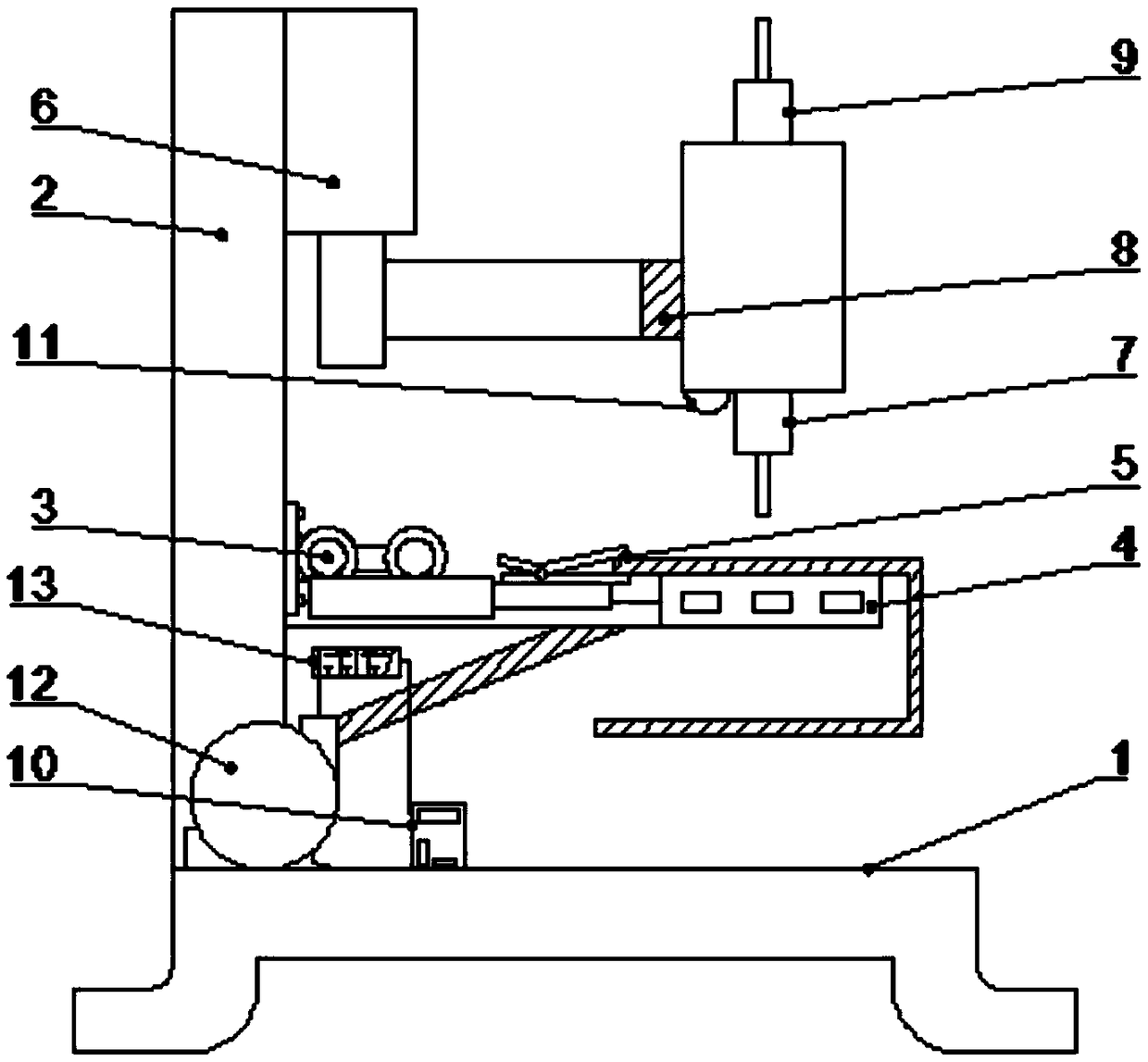
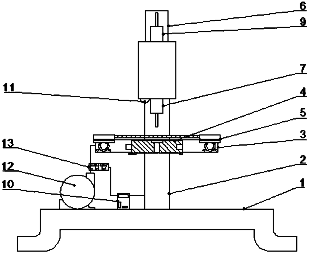
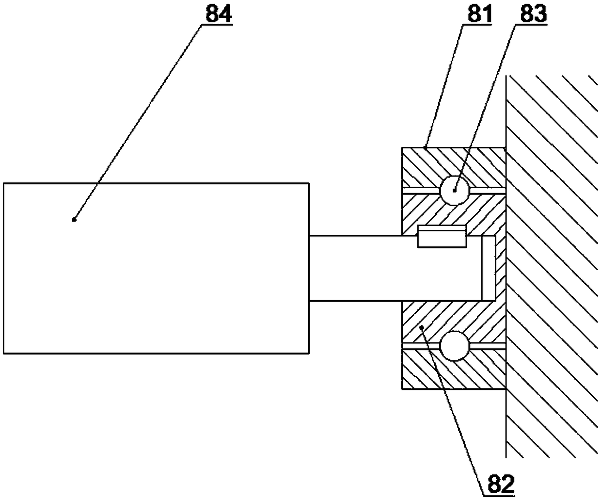

Image

  • Automatic drilling tapping machine and working method thereof
  • Automatic drilling tapping machine and working method thereof
  • Automatic drilling tapping machine and working method thereof

Examples


Embodiment 1

[0039] Such as figure 1 The shown automatic drilling and tapping machine is characterized in that it includes: a base 1, a bracket 2, a horizontal pneumatic mechanism 3, a support platform 4, a positioning clamp 5, a vertical pneumatic mechanism 6, a drilling machine 7 and a control mechanism. The base 1 is provided with a support 2, the middle section of the support 2 is provided with a horizontal pneumatic mechanism 3 and a support platform 4, the horizontal pneumatic mechanism 3 is arranged above the support platform 4, and the horizontal pneumatic mechanism 3 is provided with a positioning clip 5. The support platform 4 is provided with a through hole, the upper end of the support 2 is provided with a vertical pneumatic mechanism 6, and the vertical pneumatic mechanism 6 is provided with a drilling rig 7, and the control mechanism is connected to control the horizontal pneumatic mechanism 3 and the vertical pneumatic mechanism. Movement of body 6.

[0040] In this embodim...

Embodiment 2

[0048] Such as figure 2 The shown automatic drilling and tapping machine is characterized in that it includes: a base 1, a bracket 2, a horizontal pneumatic mechanism 3, a support platform 4, a positioning clamp 5, a vertical pneumatic mechanism 6, a drilling machine 7 and a control mechanism. The base 1 is provided with a support 2, the middle section of the support 2 is provided with a horizontal pneumatic mechanism 3 and a support platform 4, the horizontal pneumatic mechanism 3 is arranged above the support platform 4, and the horizontal pneumatic mechanism 3 is provided with a positioning clip 5. The support platform 4 is provided with a through hole, the upper end of the support 2 is provided with a vertical pneumatic mechanism 6, and the vertical pneumatic mechanism 6 is provided with a drilling rig 7, and the control mechanism is connected to control the horizontal pneumatic mechanism 3 and the vertical pneumatic mechanism. Movement of body 6.

[0049] In this embodi...

Embodiment 3

[0060] Such as image 3 The shown automatic drilling and tapping machine is characterized in that it includes: a base 1, a bracket 2, a horizontal pneumatic mechanism 3, a support platform 4, a positioning clamp 5, a vertical pneumatic mechanism 6, a drilling machine 7 and a control mechanism. The base 1 is provided with a support 2, the middle section of the support 2 is provided with a horizontal pneumatic mechanism 3 and a support platform 4, the horizontal pneumatic mechanism 3 is arranged above the support platform 4, and the horizontal pneumatic mechanism 3 is provided with a positioning clip 5. The support platform 4 is provided with a through hole, the upper end of the support 2 is provided with a vertical pneumatic mechanism 6, and the vertical pneumatic mechanism 6 is provided with a drilling rig 7, and the control mechanism is connected to control the horizontal pneumatic mechanism 3 and the vertical pneumatic mechanism. Movement of body 6.

[0061] The vertical pn...


PUM


Abstract

The invention discloses an automatic drilling tapping machine which comprises a base, a support, a horizontal pneumatic mechanism, a supporting platform, a positioning clamp, a vertical pneumatic mechanism, a drilling machine and a control mechanism. The base is provided with the support, the horizontal pneumatic mechanism and the supporting platform are arranged on the middle portion of the support, the horizontal pneumatic mechanism is provided with the positioning clamp, the vertical pneumatic mechanism is arranged at the upper end of the support, the drilling machine is arranged on the vertical pneumatic mechanism, and the control mechanism is connected with and controls the horizontal pneumatic mechanism and the vertical pneumatic mechanism. The invention further discloses a working method of the automatic drilling tapping machine. An automatic control system is adopted for avoiding the current condition of manual operation, the working content is simplified, manual cost is reduced, comprehensive automation is achieved, and the working efficiency and the safety are improved; supporting plane modularization is carried out so that the machine can be suitable for plates with different sizes and different space shapes, the using scope of the equipment is enlarged, and the automatic drilling tapping machine better meets the enterprise need.

Description

technical field [0001] The invention belongs to the field of sheet metal processing equipment, in particular to an automatic drilling and tapping machine and a working method thereof. Background technique [0002] Automation is a high-tech company specializing in the R&D, production and sales of intelligent automatic control, digital and networked controllers and sensors. Its numerous functional modules and perfect embedded solutions can meet the individual needs of many users to the greatest extent. . With the development of industry and the progress of science and technology, we can see that the production of manufacturing industry is gradually moving towards full automation. In the current workshop, various numerical control equipment and automation equipment are replacing old-fashioned manual or semi-automatic production equipment. With the increase of labor costs, the advantages of automation equipment are more prominent. It will become a trend for automation equipme...

Claims


Application Information

Patent Timeline
Patent Type & Authority Applications(China)
IPC IPC(8): B23P23/02B23Q1/25B23Q17/00
CPCB23P23/02B23Q1/25B23Q17/00
Inventor 严立兵葛中雨
Owner 卓弢机器人盐城有限公司
Why Eureka
Eureka Blog
Learn More