Digital printing equipment using ceramic powder

A digital printing and ceramic powder technology, applied in the field of digital printing, can solve the problems of low precision, mixing materials, and blurred brick surface patterns, etc., and achieve the effects of efficient use of space, simplified gas path connection, and small size

Pending Publication Date: 2018-12-07
FOSHAN SAPFIT MACHINERY CO LTD +1
View PDF0 Cites 3 Cited by
  • Summary
  • Abstract
  • Description
  • Claims
  • Application Information

AI Technical Summary

Problems solved by technology

At present, in terms of the production methods of ceramic tiles, the production of patterned ceramic tiles usually adopts a material distribution method that combines material pipes, hoppers, and powder conveyor belts. The control accuracy of the material is low, and the precision of the generated pattern lines and colors is low. The pattern is not enough Realistic, and at the same time, it is easy to mix materials, which makes the pattern of the brick surface blurred and affects the production quality; in order to improve the accuracy, some technicians apply the analog printing method to the production of ceramic tile patterns, but the analog printing generally uses ink, and the brick surface is imaged There is no three-dimensional effect, and it is difficult to meet the needs of consumers. In order to solve the above problems, it is urgent to design a device that can print patterns on the surface of ceramic tiles with high precision, easy control, and a three-dimensional printing effect.

Method used


Image

  • Digital printing equipment using ceramic powder
  • Digital printing equipment using ceramic powder
  • Digital printing equipment using ceramic powder

Examples


Embodiment Construction

[0021] Embodiments of the present invention are described in detail below, examples of which are shown in the drawings, wherein the same or similar reference numerals designate the same or similar elements or elements having the same or similar functions throughout. The embodiments described below by referring to the figures are exemplary and are intended to explain the present invention and should not be construed as limiting the present invention.

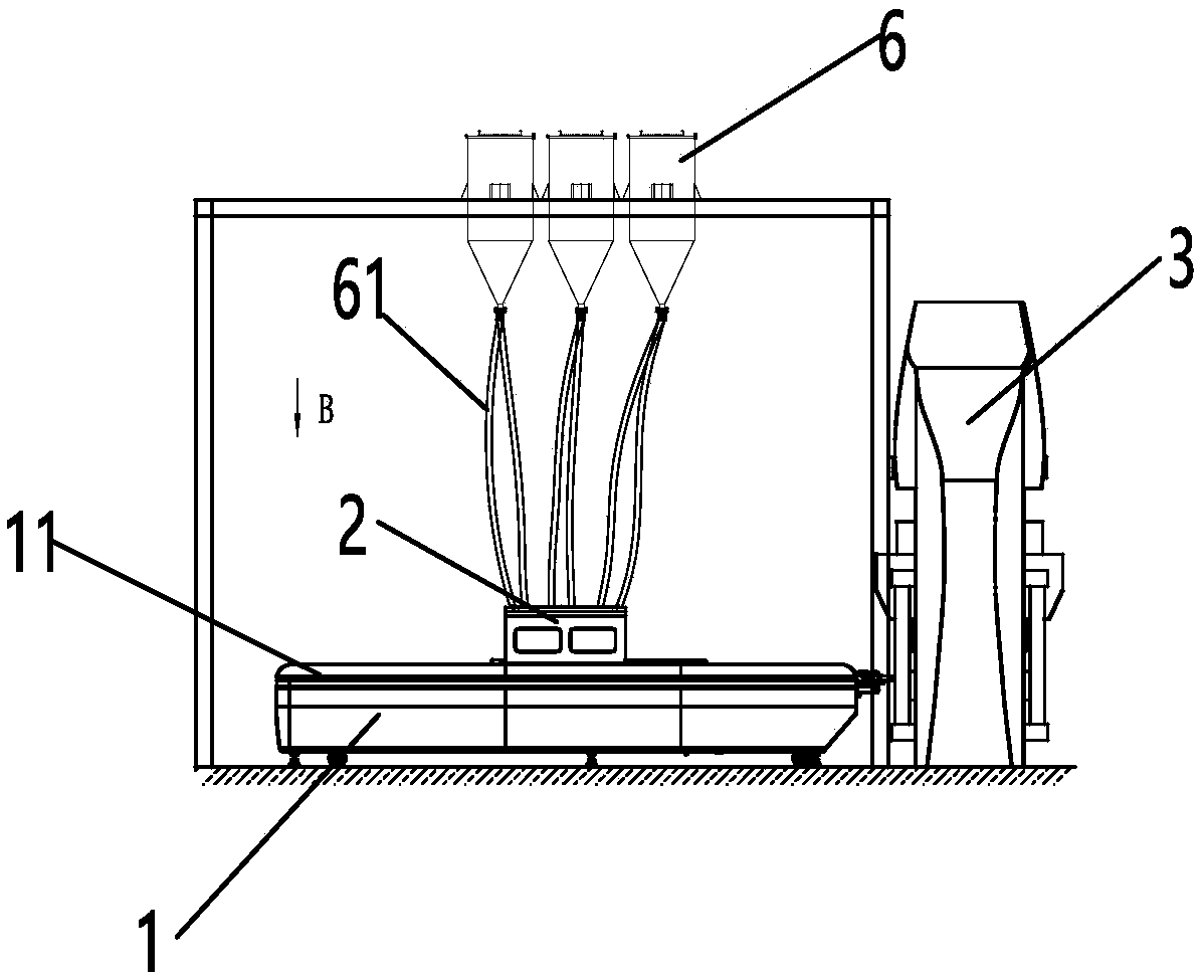
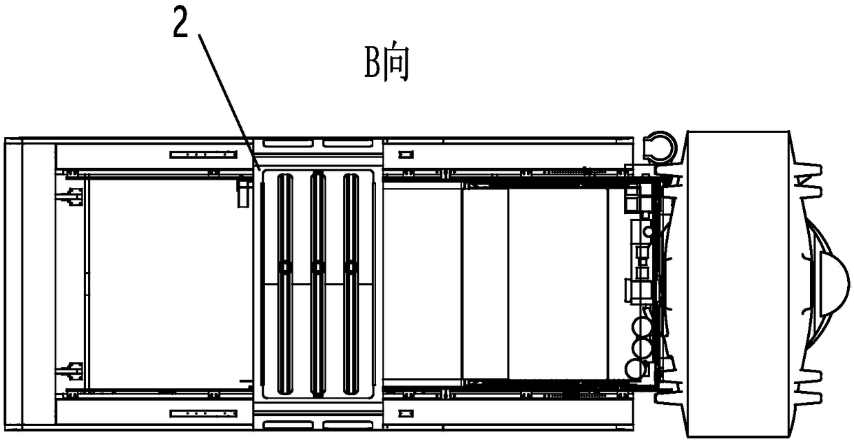
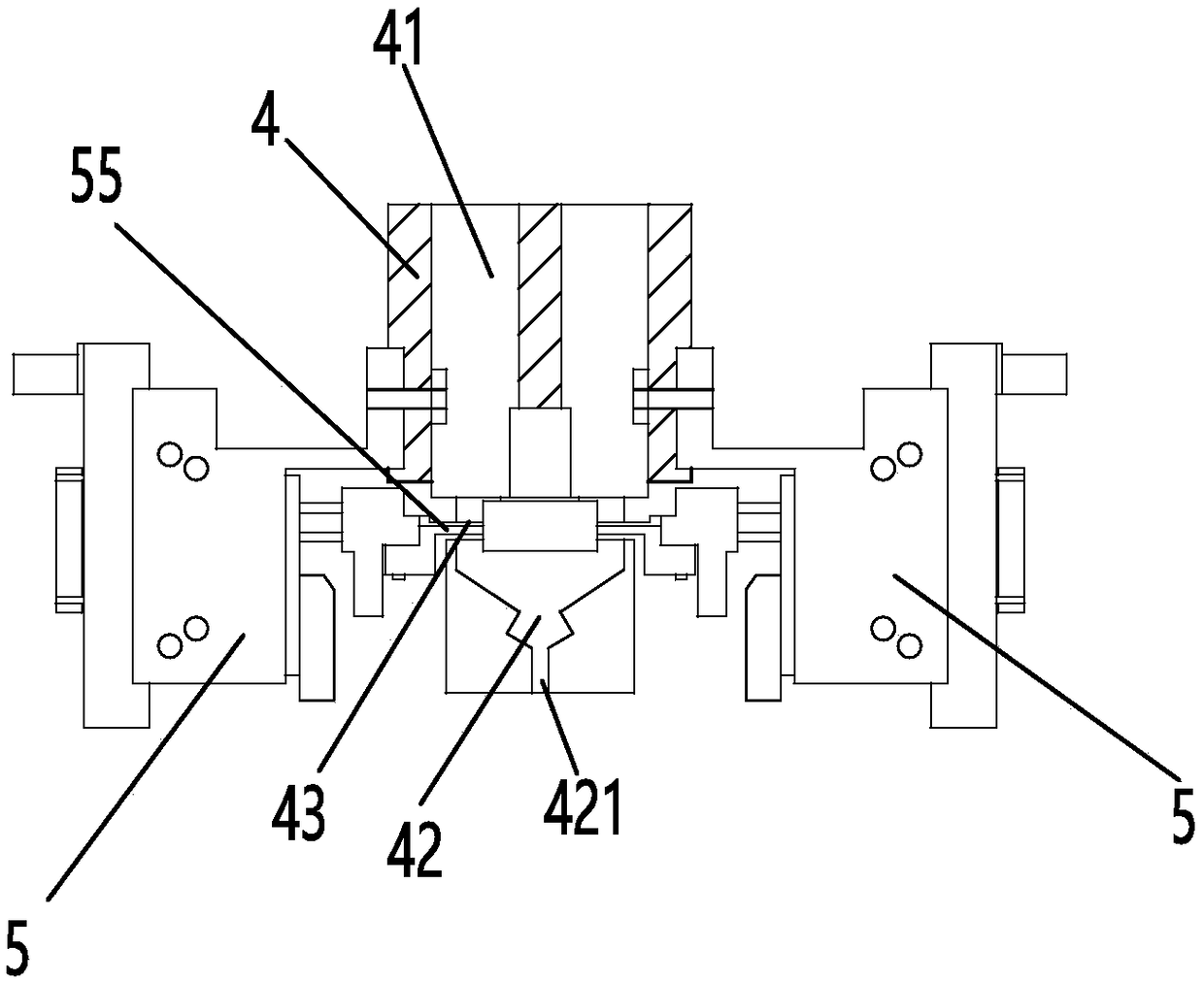
[0022] refer to figure 1 , figure 2 , image 3 and Figure 4 , a digital printing device using ceramic powder, including a base 1, a blanking mechanism 2, and a control device 3, the base 1 includes a conveying device 11; the blanking mechanism 2 is installed above the conveying device 11, The blanking mechanism 2 includes a hopper 4 and an integrated pneumatic device 5 that controls the blanking of the hopper 4; the hopper 4 includes a storage chamber 41 for storing powder, and is located below the storage chamber 41 The fu...


PUM


Abstract

The invention discloses digital printing equipment using ceramic powder. The digital printing equipment comprises a base, a dropping mechanism and a control device; the base comprises a conveying device; the dropping mechanism is installed on the conveying device and comprises a hopper and an integrated pneumatic device for controlling dropping of the hopper; the digital printing equipment is usedfor conducting printing on the surface of a ceramic tile, different points are controlled to conduct dropping at the same time through the integrated pneumatic device, the control device controls different release openings to conduct dropping and controls the dropping time through the integrated pneumatic device, a tile body is driven to move through the conveying device, and different patterns are formed on the surface of the tile, that is, printing is completed; the integrate pneumatic device comprises a shell body, a plurality of metal pistons installed in the shell body, and a solenoid valve for controlling the metal pistons; and the integrate pneumatic device achieves the effect that the multiple metal pistons are integrated together, independent working of the multiple metal pistonsis completed through a special gas channel structure in the device and the solenoid valve, gas channel connection is simplified, the whole device is small in size, and the spatial position is efficiently utilized.

Description

technical field [0001] The invention relates to the field of digital printing, in particular to a digital printing device using ceramic powder. Background technique [0002] With the improvement of people's aesthetic level, the requirements for the decorative effect of ceramic tiles are also constantly increasing. It is hoped that the decorative patterns on the brick surface will be rich and precise. At present, in terms of the production methods of ceramic tiles, the production of patterned ceramic tiles usually adopts a material distribution method that combines material pipes, hoppers, and powder conveyor belts. The control accuracy of the material is low, and the precision of the generated pattern lines and colors is low. The pattern is not enough Realistic, and at the same time, it is easy to mix materials, which makes the pattern of the brick surface blurred and affects the production quality; in order to improve the accuracy, some technicians apply the analog printing...

Claims


Application Information

Patent Timeline
IPC IPC(8): B28B11/00
CPCB28B11/001
Inventor 陈锦杨学先邓伟丁有馀
Owner FOSHAN SAPFIT MACHINERY CO LTD
Why Eureka
Try Eureka