Zero rear thrust composite-wing cargo aircraft with turbofan composite ailerons and additional wings

A composite wing and aircraft technology, applied in the field of aircraft, can solve the problems of low wing structure strength, unsatisfactory controllability, slow horizontal flight speed, etc., to expand the wing area, facilitate cluster flight, and fly fast. Effect

Inactive Publication Date: 2018-12-07
JIANGSU CHANGTAN ROBOT CO LTD
View PDF9 Cites 0 Cited by
  • Summary
  • Abstract
  • Description
  • Claims
  • Application Information

AI Technical Summary

Problems solved by technology

The traditional fixed wing has the advantages of fast flight speed, low energy consumption, etc., but it has the disadvantages that the main wing and the horizontal tail are not connected front and rear, the wing structure is not strong, easy to be damaged, the take-off and landing requirements are high, and the take-off and landing distance is long; the traditional vertical The take-off and landing aircraft has the advantages of convenient take-off and landing, but has the disadvantages of high energy consumption, low safety factor, poor load capacity, slow horizontal flight speed, and easy crash; although the current vertical take-off and landing fixed wing has the characteristics of convenient take-off and landing , but the controllability is not ideal when flying horizontally, and there are disadvantages such as large flight resistance, high energy consumption, and low safety factor.

Method used


Image

  • Zero rear thrust composite-wing cargo aircraft with turbofan composite ailerons and additional wings
  • Zero rear thrust composite-wing cargo aircraft with turbofan composite ailerons and additional wings
  • Zero rear thrust composite-wing cargo aircraft with turbofan composite ailerons and additional wings

Examples


Embodiment Construction

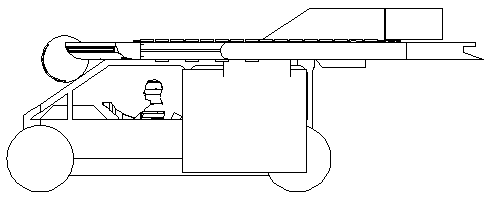
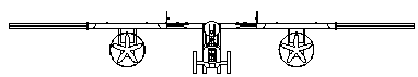
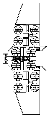
[0030] Such as Figure 1 to Figure 5 As shown, the non-rear-thrust type compound-wing cargo aircraft with turbofan composite auxiliary wings and additional wings is characterized in that it is composed of a non-rear-thrust type compound-wing aircraft and a turbofan thrust self-powered composite Auxiliary wing, additional wing 114 and freight warehouse 113 are formed; Wherein, described non-rear-thrust type composite wing aircraft comprises body 101, is fixedly installed in body 101 both sides composite lift wing 102; Wherein, wherein, described body 101 It is set as a deck platform; the front of the body 101 is provided with a camera 108, and the self-enclosed ducted fan 104 is built into the composite lift wing 102, and a wing hinge (1028) is designed on the outside of the composite lift wing 102; the turbofan thrust A turbofan propeller 1064 is arranged below the self-powered composite aileron, a self-enclosed ducted fan 104 is arranged inside the turbofan thrust self-powe...


PUM


Abstract

The invention provides a zero rear thrust composite-wing cargo aircraft with turbofan composite ailerons and additional wings. An aircraft body is arranged as a deck platform; a self-sealing ducted fans are embedded in composite lift wings; wing hinges are designed on the external sides of the composite lift wings; turbofan propellers are arranged under turbofan thrust self-energized composite ailerons; self-sealing ducted fans are arranged in the turbofan thrust self-energized composite ailerons; electricity, liquid and gas interfaces and wing hinges are arranged on one sides or two sides ofthe turbofan thrust self-energized composite ailerons; the turbofan thrust self-energized composite ailerons are movably connected with the composite lift wings through the wing hinges; wing hinges are arranged on one sides, facing towards the aircraft body, of the additional wings; the additional wings are mounted on the external sides of the composie lift wings through the wing hinges in a foldable manner; and a cargo compartment is mounted at the bottom of the aircraft body. The zero rear thrust composite-wing cargo aircraft with the turbofan composite ailerons and the additional wings hasthe advantages that the taking-off and landing distance is short, the flying speed is high, the structural strength of the wings is high, the wings can store energy, the flying energy consumption is low, the hang time is long, the safety is high, the ailerons adopt composite lift forces to guarantee the power application range and so on.

Description

technical field [0001] The invention relates to an aircraft, in particular to a non-rear thrust composite wing cargo aircraft with a turbofan compound auxiliary wing and an additional wing, belonging to the technical field of aircraft equipment. Background technique [0002] Existing aircraft are mainly divided into two categories: fixed-wing and vertical take-off and landing aircraft (such as helicopters and multi-rotors). Of course, there is also a vertical take-off and landing fixed-wing product. The traditional fixed wing has the advantages of fast flight speed, low energy consumption, etc., but it has the disadvantages that the main wing and the horizontal tail are not connected front and rear, the wing structure is not strong, easy to be damaged, the take-off and landing requirements are high, and the take-off and landing distance is long; the traditional vertical The take-off and landing aircraft has the advantages of convenient take-off and landing, but has the disa...

Claims


Application Information

Patent Timeline
Patent Type & Authority Applications(China)
IPC IPC(8): B64C27/20B64C27/26B64C37/02
Inventor 任曲波
Owner JIANGSU CHANGTAN ROBOT CO LTD
Why Eureka
Try Eureka