
An intelligent takeoff and landing platform of an unmanned aerial vehicle

A take-off and landing platform, witty technology, applied in the field of unmanned aerial vehicles, can solve the problems of unmanned aerial vehicles not landing accurately, unmanned aerial vehicle impact damage, high labor intensity, etc., to achieve smooth rise and fall, reduce labor intensity, and high labor intensity Effect

Active Publication Date: 2018-12-07
北京腾益电力科技有限公司
View PDF6 Cites 2 Cited by
  • Summary
  • Abstract
  • Description
  • Claims
  • Application Information

AI Technical Summary

Problems solved by technology

[0003] In order to solve the above problems, the present invention provides a UAV intelligent landing platform, which can solve the problem that when the existing UAV lands, the UAV cannot be accurately landed at the designated position due to insufficient personnel control. Placed on the ground, the placement is unstable. When the UAV falls to the ground due to a fault during flight, due to the different terrain, the UAV itself will be impacted and damaged when it lands. The process takes a long time, labor intensity is high and efficiency is low. , can realize the function of stable take-off and landing of the UAV and reduce the impact damage during emergency landing, accurately land on the landing platform device, the landing platform device is placed stably, and make targeted adjustments according to the terrain conditions to ensure that it can be used in the event of a failure. Stable landing on the ground, automatic cushioning during emergency landing, short time-consuming, and has the advantages of simple operation, low labor intensity and high work efficiency

Method used


Image

  • An intelligent takeoff and landing platform of an unmanned aerial vehicle
  • An intelligent takeoff and landing platform of an unmanned aerial vehicle
  • An intelligent takeoff and landing platform of an unmanned aerial vehicle

Examples


Embodiment Construction

[0031] In order to make the technical means, creative features, goals and effects achieved by the present invention easy to understand, the present invention will be further described below in conjunction with specific illustrations. It should be noted that, in the case of no conflict, the embodiments in the present application and the features in the embodiments can be combined with each other.

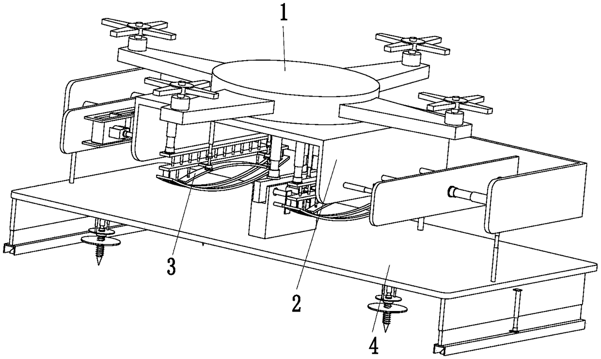
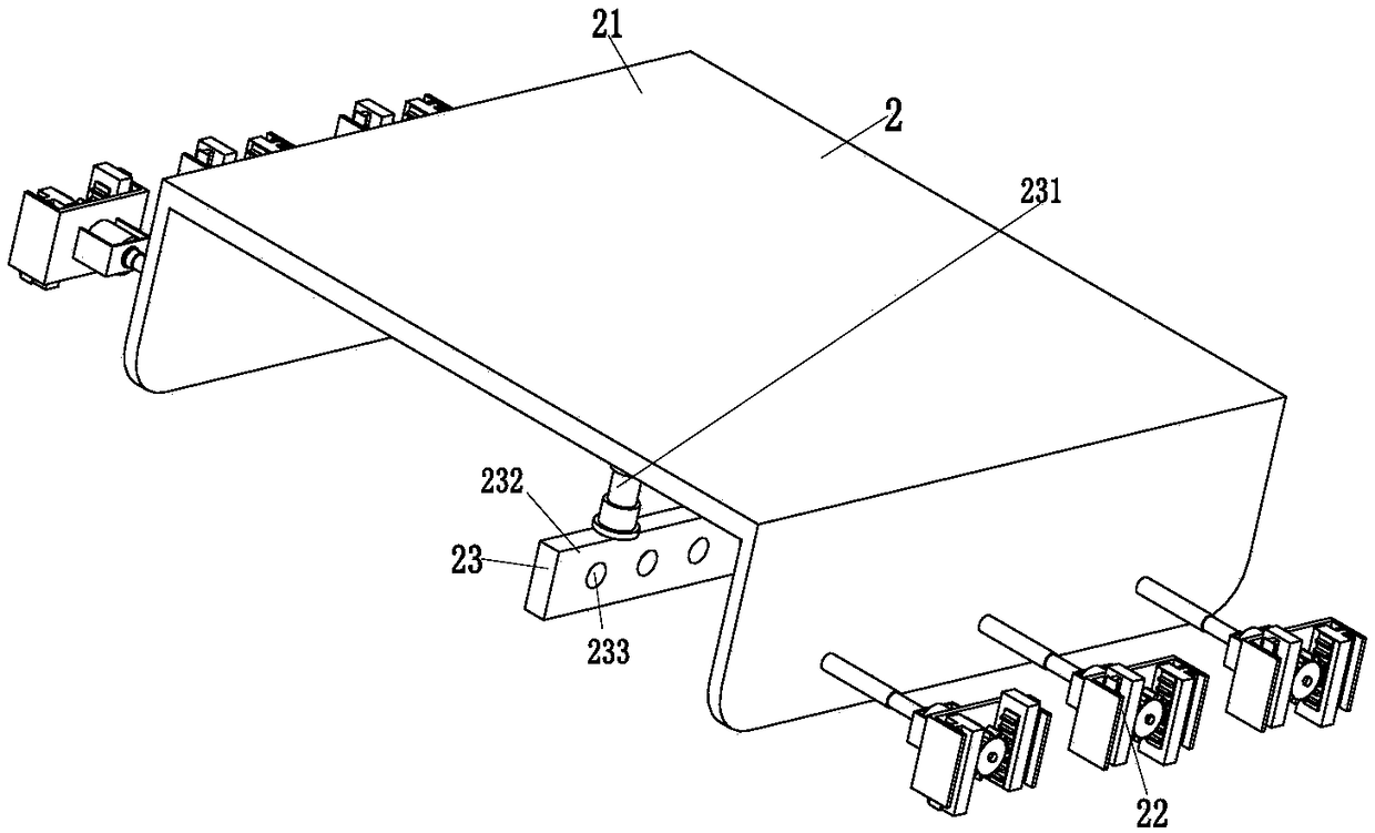
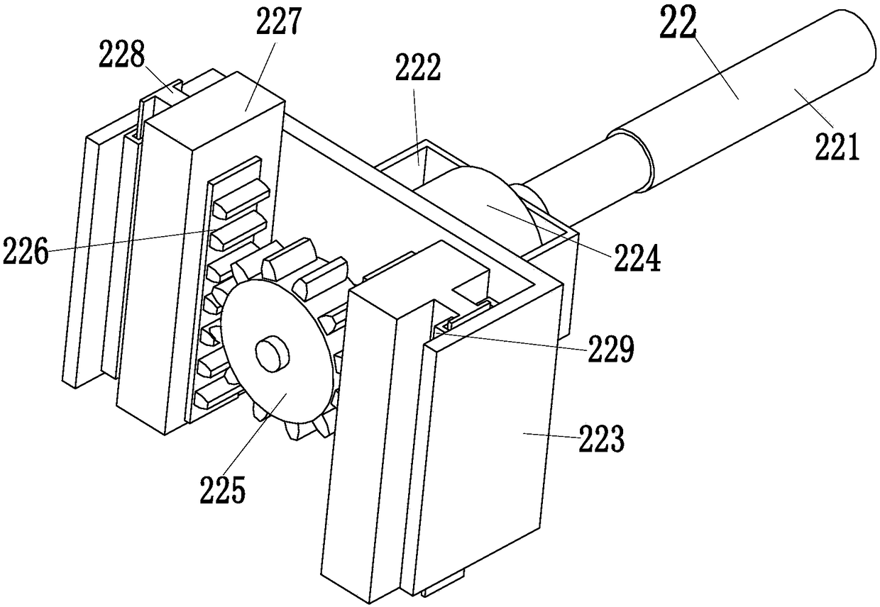
[0032] Such as Figure 1 to Figure 6 As shown, a UAV intelligent take-off and landing platform includes a body 1, a docking device 2, two temporary landing devices 3 and a landing platform device 4, and the above landing platform device 4 is provided with a docking device 2, and the docking device The lower end of 2 is equipped with two temporary landing gear 3, and two temporary landing gear 3 is positioned at the top of landing platform device 4, and the upper end of docking device 2 is installed organic body 1.

[0033] The docking device 2 includes a U-shaped main frame 21, a lo...


PUM


Abstract

The invention relates to an intelligent take-off and landing platform of an unmanned aerial vehicle, which comprises an airframe, a parking device, two temporary landing devices and a landing platformdevice, wherein the parking device is arranged above the landing platform device, the two temporary landing devices are installed at the lower end of the parking device, the two temporary landing devices are located above the landing platform device, and the airframe is installed at the upper end of the parking device. The problems that as the exist unmanned aerial vehicle landing, uncorrected operation prevents the UAV from landing exactly where it was intended, existing landing platforms are usually placed directly on the ground, the placement is instable, when the UAV falls to the ground due to the fault in the flight process, the UAV itself will be damaged by impact due to the different terrain, the process takes a long time, the labor intensity is large and the efficiency is low canbe solved, and the functions of taking off and landing the UAV steadily and reducing the impact damage in the emergency landing are realized.

Description

technical field [0001] The invention relates to the field of unmanned aerial vehicles, in particular to an intelligent landing platform for unmanned aerial vehicles. Background technique [0002] UAV is a kind of unmanned flying equipment controlled by radio remote control or self-contained program. There is no cockpit on board, but equipment such as autopilot and program control device are installed. Ground personnel use radar and other equipment to track, locate, remote control, telemeter and digitally transmit drones. According to the application field, they can be divided into military and civilian. Civilian UAVs have very broad application prospects in the fields of aerial photography, agriculture, and surveying and mapping; however, when the existing UAVs land, the lack of human control prevents the UAVs from accurately landing at the designated location, and the existing landing platforms usually directly Placed on the ground, the placement is unstable. When the UAV...

Claims


Application Information

Patent Timeline
Patent Type & Authority Applications(China)
IPC IPC(8): B64F1/00
CPCB64F1/00
Inventor 陈妹儿
Owner 北京腾益电力科技有限公司
Learn More