
Manual inspection device for safety belt of vehicle

An inspection device and seat belt technology, which is applied in the field of manual inspection of vehicle seat belts, can solve problems such as product defects and undiscovered defects, hidden quality problems, and easy fatigue

Inactive Publication Date: 2018-12-07
滑县浩之本网络科技有限公司
View PDF1 Cites 1 Cited by
  • Summary
  • Abstract
  • Description
  • Claims
  • Application Information

AI Technical Summary

Problems solved by technology

[0004] However, the winding device in this technical solution is manually inspected during the continuous winding process. When the workers check the defects on the safety belts during the movement, the workers are prone to fatigue and cause the defects and defects of the products to be undiscovered. Unqualified The seat belt leaves the factory to the user, which leads to the problem of hidden quality

Method used


Image

  • Manual inspection device for safety belt of vehicle
  • Manual inspection device for safety belt of vehicle
  • Manual inspection device for safety belt of vehicle

Examples


Embodiment 1

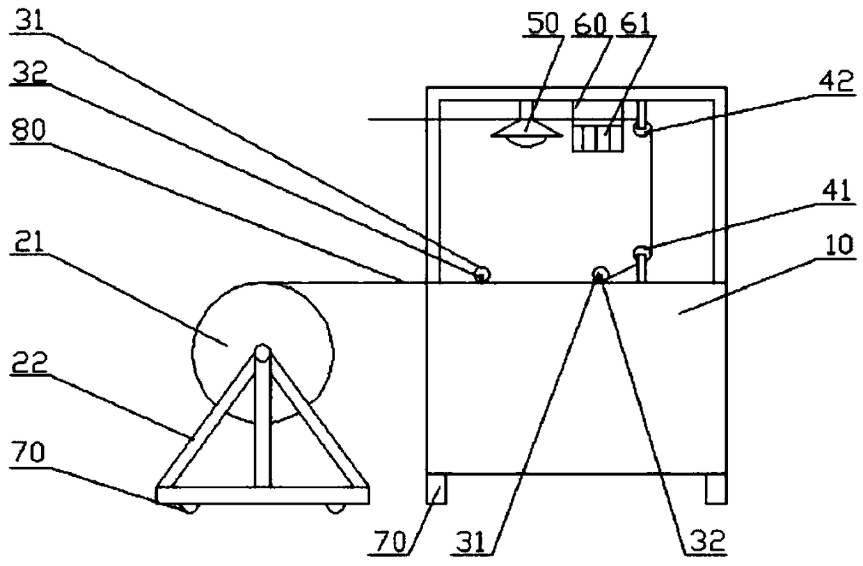
[0030] A safety belt manual inspection device for vehicles, which includes a frame, a conveying mechanism for transporting seatbelts to it, a lighting lamp and a label box, and the conveying mechanism, lighting lamp and label box are all arranged on the frame, and the The conveying mechanism is used to wind up the safety belt, the lighting lamp is used to provide a light source, and the label box is used to provide a label for identifying the position of the defect, and the conveying mechanism includes an intermittent transmission mechanism, and the intermittent transmission mechanism is used for Intermittent driving force is provided to realize the rotation state and stop state of the conveying mechanism within one rotation cycle.

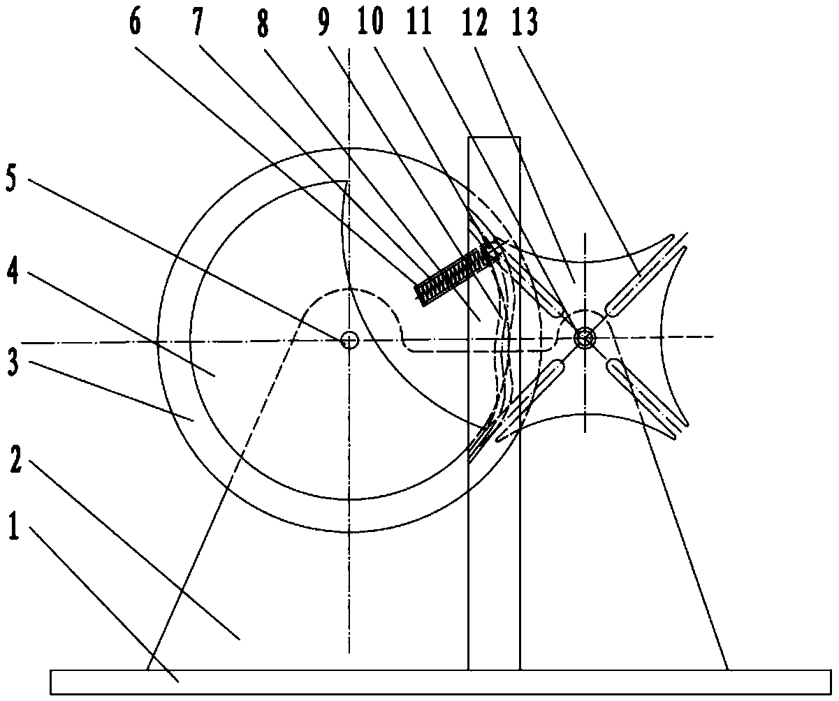
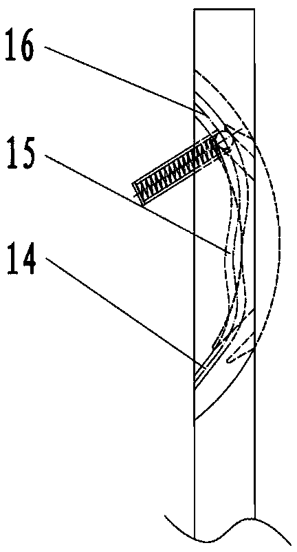
[0031] Such as Figure 2-3 As shown, the intermittent transmission mechanism includes a base plate 1, a bracket 2, a driving turntable 3, a positioning turntable 4, a first rotating shaft 5, a spring support frame 6, a spring 7, a guide frame 8, a...

Embodiment 2

[0042] A safety belt manual inspection device for vehicles, comprising a frame and a conveying mechanism for transporting seat belts thereto, lighting lamps and label boxes, the conveying mechanism, lighting lamps and label boxes are all arranged on the frame, the The conveying mechanism is used to wind up the safety belt, the illuminating lamp is used to provide a light source, and the label box is used to provide labels for identifying defect positions. The conveying mechanism includes an intermittent transmission mechanism, and the intermittent transmission mechanism is used to provide Intermittent driving force is used to realize the conveying mechanism having two rotation states and two stop states within one rotation cycle.

[0043] Such as Figure 2-3 As shown, the intermittent transmission mechanism includes a base plate 1, a bracket 2, a driving turntable 3, a positioning turntable 4, a first rotating shaft 5, a spring support frame 6, a spring 7, a guide frame 8, a g...


PUM


Abstract

The invention discloses a manual inspection device for a safety belt of a vehicle. The manual inspection device comprises a rack, a conveying mechanism, an illuminating lamp and a label box, wherein the conveying mechanism is used for conveying the safety belt to the rack; the conveying mechanism, the illuminating lamp and the label box are all arranged on the rack; the conveying mechanism is usedfor rolling the safety belt; the illuminating lamp is used for providing a light source; the label box is used for providing a label for identifying flaw locations; the conveying mechanism comprisesan intermittent drive mechanism; and the intermittent drive mechanism is used for providing intermittent drive force to achieve the purpose that the conveying mechanism has a rotating state and a stopping state in a rotation period. A cylindrical surface on the outermost side of a locating turntable begins to be in contact with an arc-shaped locating groove in a driving turntable, so that the rotation of the driving turntable is stopped, the position of the driving turntable is located, a roller stops rotating, and the safety belt stops rolling to facilitate the manual inspection of the safetybelt.

Description

technical field [0001] The invention belongs to the technical field of safety belt manual inspection of vehicles, in particular to a safety belt manual inspection device for vehicles. Background technique [0002] The seat belt is an important part to ensure the safety of the driver during the driving of the vehicle. In the quality inspection link after the seat belt is produced, ensuring the quality of the seat belt is of great importance to the safety of the driver. The existing safety belt inspection work is performed by the winding equipment for automatic winding and unwinding, and then the flaws and defects of the safety belts are manually inspected during the winding and unwinding process, so as to ensure that the safety belts leaving the factory are all qualified products. The inspection to safety belt in the prior art has: [0003] Notification No.: CN106017267A, Publication Date: October 12, 2016 The patent document records a safety belt visual inspection device, ...

Claims


Application Information

Patent Timeline
IPC IPC(8): B65H26/02B65C9/40G01M17/007
CPCB65H26/02B65C9/40B65H2701/192G01M17/007
Inventor 王志国
Owner 滑县浩之本网络科技有限公司
Learn More