Drill bit heat treatment equipment for mine

A technology of heat treatment equipment and drill bits, which is applied in the direction of heat treatment equipment, heat treatment furnaces, furnaces, etc., can solve the problems of drill bit strength and wear resistance deviation, affect mineral excavation, and reduce the number of drill bits produced, so as to save production time and ensure processing Temperature, the effect of preventing excessive temperature

Inactive Publication Date: 2018-12-07
金双悦
View PDF0 Cites 1 Cited by
  • Summary
  • Abstract
  • Description
  • Claims
  • Application Information

AI Technical Summary

Problems solved by technology

[0002] As a relatively important resource, minerals have always been valued by the country. The mining of minerals is an important guarantee for the effective use of mineral resources. Drills must be used for mining. Therefore, the material of this drill must have high strength and wear resistance. Due to the The heat treatment process plays a decisive role in the performance of the drill bit, so the heat treatment process of the drill bit is the key to ensure the strength and wear resistance; at this stage, when the heat treatment of the drill bit is manually operated, the heating time and temperature cannot be effectively guaranteed, so The strength and wear resistance of drill bits tend to deviate, which affects the mining effect; in the process of using mechanical operations, most equipment can only process one drill bit at a time at this stage, thus greatly reducing the production quantity of drill bits and affecting the excavation of minerals

Method used


Image

  • Drill bit heat treatment equipment for mine
  • Drill bit heat treatment equipment for mine
  • Drill bit heat treatment equipment for mine

Examples


Embodiment Construction

[0017] The following will clearly and completely describe the technical solutions in the embodiments of the present invention with reference to the accompanying drawings in the embodiments of the present invention. Obviously, the described embodiments are only some, not all, embodiments of the present invention. All other embodiments obtained by persons of ordinary skill in the art based on the embodiments of the present invention belong to the protection scope of the present invention.

[0018] According to an embodiment of the present invention, heat treatment equipment for drill bits used in mines is provided.

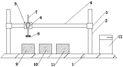
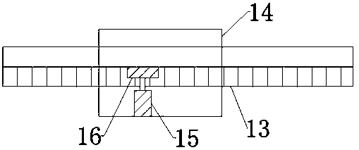
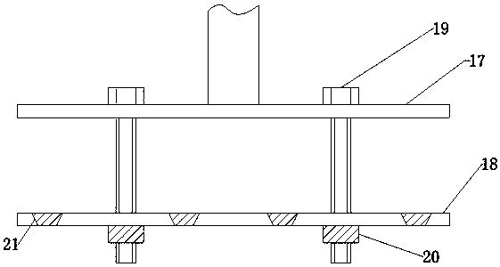
[0019] Such as Figure 1-3 As shown, the drill bit heat treatment equipment for mining according to the embodiment of the present invention includes a workbench 1, a fixed support 2 is fixed above the workbench 1, and a controller 12 is arranged on one side of the fixed support 2, and the controller 12 is fixed to the workbench 1. Connection, through the action of ...


PUM


Abstract

The invention discloses drill bit heat treatment equipment for a mine. The drill bit heat treatment equipment comprises a working platform. A fixing supporting bracket is fixedly arranged above the working platform. A controller is arranged on one side of the fixing supporting bracket. A lifting block is arranged on one side of the fixing supporting bracket in a sleeving mode. A horizontal guide rod is fixedly arranged on the inner side of the lifting block. A moving device is arranged on one side of the horizontal guide rod. A telescopic motor is fixedly arranged on one side of the moving device. A telescopic rod is arranged on the inner side of the telescopic motor. A drill bit fixing device is fixedly arranged below the telescopic rod. The drill bit heat treatment equipment has the beneficial effects that through cooperation between the lifting block and the moving device, movement of the drill bit fixing device can be achieved, and three processes of heat treatment can be achieved.Through action of the telescopic motor and the telescopic rod, distance between the telescopic motor and a working station can be retained to prevent motor damage caused by excessive temperature of the telescopic motor due to too close distance. Through the drill bit fixing device, a drill bit can be fixed, and therefore heat treatment of the drill bit can be convenient, a plurality of drill bitscan be treated at the same time, and production time of the drill bit can be shortened.

Description

technical field [0001] The invention relates to the technical field of heat treatment of drill bits used in mines, in particular to a heat treatment equipment for drill bits used in mines. Background technique [0002] As a relatively important resource, minerals have always been valued by the country. The mining of minerals is an important guarantee for the effective use of mineral resources. Drills must be used for mining. Therefore, the material of this drill must have high strength and wear resistance. Due to the The heat treatment process plays a decisive role in the performance of the drill bit, so the heat treatment process of the drill bit is the key to ensure the strength and wear resistance; at this stage, when the heat treatment of the drill bit is manually operated, the heating time and temperature cannot be effectively guaranteed, so The strength and wear resistance of drill bits often have deviations, which affect the mining effect; in the process of mechanical...

Claims


Application Information

Patent Timeline
Patent Type & Authority Applications(China)
IPC IPC(8): C21D9/22C21D1/62
CPCC21D9/22C21D1/62C21D9/0062
Inventor 金双悦
Owner 金双悦
Why Eureka
Try Eureka