Multi-functional pile foundation model test box device and using method thereof

A model test, multi-functional technology, applied in the test of the foundation structure, the measurement device, the use of stable tension/pressure to test the strength of the material, etc. It can solve the problems of time-consuming and laborious, laborious foundation soil excavation, and large depth of the model box. , to achieve the effect of improving test efficiency, reducing workload and easy handling

Active Publication Date: 2018-12-07
CHONGQING UNIV
View PDF8 Cites 11 Cited by
  • Summary
  • Abstract
  • Description
  • Claims
  • Application Information

AI Technical Summary

Problems solved by technology

In order to obtain a larger burial depth, the depth of the model box is relatively large, and it is laborious for the testers to pull out the foundation soil from the lower part of the box, and even requires the testers to jump into the narrower model to get the soil, which is still time-consuming and laborious under the cooperation of multiple people

Method used


Image

  • Multi-functional pile foundation model test box device and using method thereof
  • Multi-functional pile foundation model test box device and using method thereof
  • Multi-functional pile foundation model test box device and using method thereof

Examples


Embodiment 1

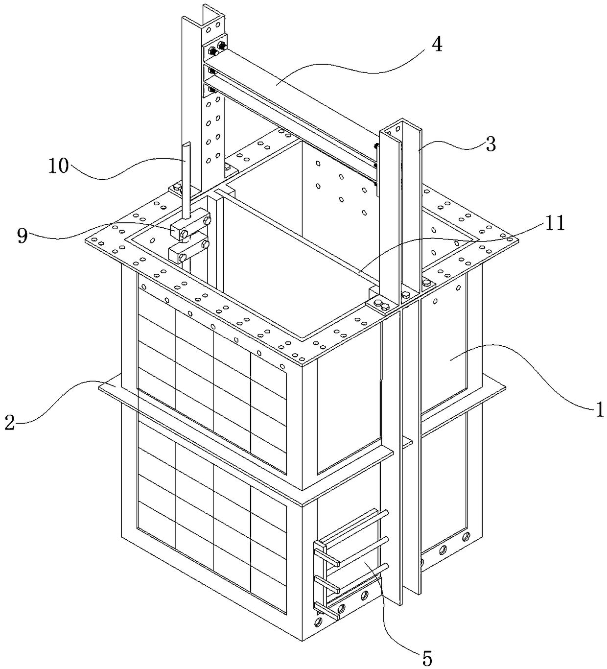
[0058] see figure 1 , the present embodiment discloses a multifunctional pile foundation model test box device, including a plexiglass box 1, a box supporting steel frame 2, two movable supports 3 and a movable reaction beam 4.

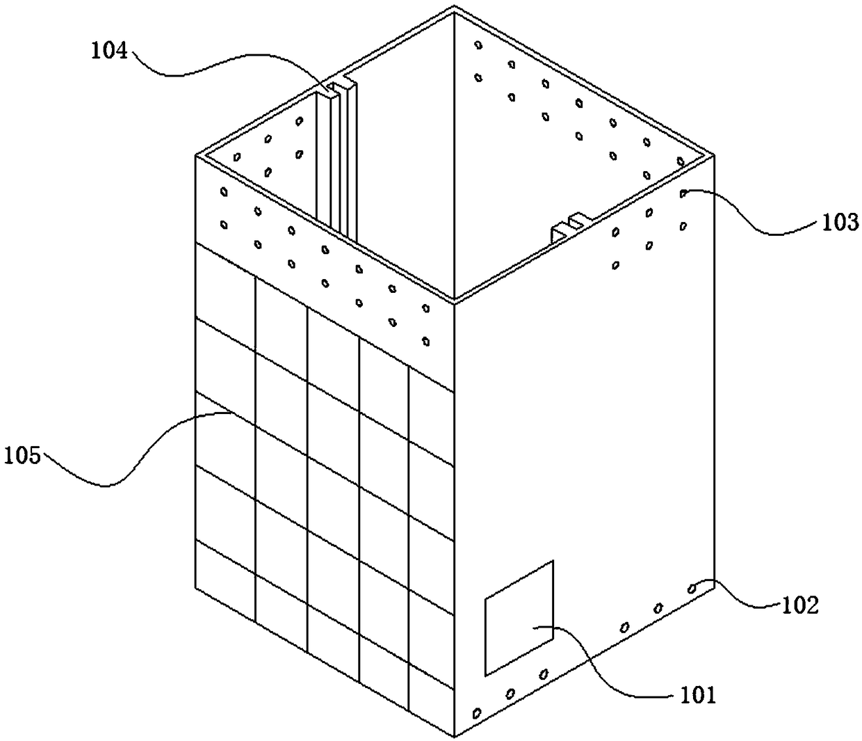
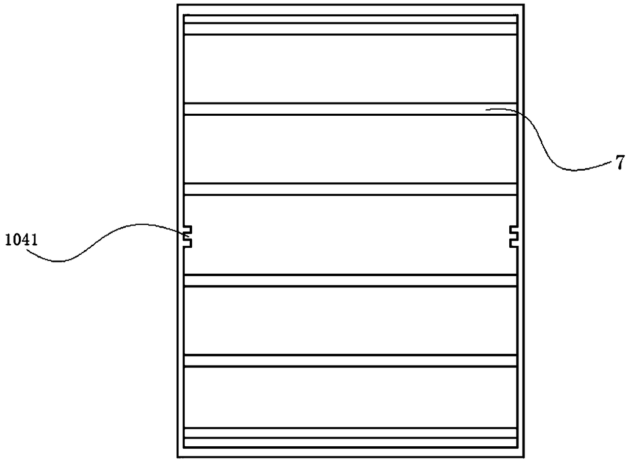
[0059] see figure 2 and image 3 , the plexiglass box 1 as a whole is a rectangular box with an open upper end and a hollow interior. The four side walls of the rectangular box are sequentially the first side panel, the second side panel, the third side panel and the fourth side panel. The plate surfaces of the four side walls are all provided with two rows of model pile limiting holes 103 according to the design. The model pile limit hole 103 is arranged at the upper end of the wall. A scale line 105 is provided on the surface of the second side plate or the fourth side plate. The inner wall of the first side plate and the third side plate is vertically provided with a middle partition limiting strip 104 . The limiting bar 104 of the intermedi...

Embodiment 2

[0065] This embodiment discloses a method for using the multifunctional pile foundation model test box device described in Embodiment 1, see Figure 14 , including the following steps:

[0066] 1) Design model pile I8 and model pile II10 according to the test requirements. And paste strain gauges on the surface of model pile I8 and model pile II10. Among them, see Figure 9 and Figure 11 , the model pile I8 is a cylinder, and the model pile II10 is a semi-cylindrical. In this embodiment, the diameter of the pile bodies of the model pile I8 and the model pile II10 are both D, and the heights are both 12D.

[0067] 2) Use a brush to clean the plexiglass model box 1. Insert the discharge door 5 into the discharge port 101. Connect the water outlet valve with the water outlet hole 102.

[0068] 3) Connect the data acquisition equipment and the sensor, and debug to ensure that the sensor works normally. Wherein, the sensor includes a strain gauge and an earth pressure cell...


PUM


Abstract

The invention provides a multi-functional pile foundation model test box device and a using method thereof. The test box device comprises an organic glass box body, a box body supporting steel frame,movable supporting seats and a movable counter force beam. The organic glass box body is put in the box body supporting steel frame, the lower portion of the box body supporting steel frame is provided with plug pin fixing holes so that a discharging door can be fixed, the movable supporting seats are arranged on an upper steel plate reinforcing hoop of the supporting steel frame, and the movablecounter force beam is arranged between the two movable supporting seats. The using method of the test box device comprises the steps of debugging preparation, sensor arrangement, pile burying, box interior position round column pile vertical loading, box wall semi-pile pile sinking soil squeezing testing and the like. The test box device is low in weight, good in part detachable performance, easyto carry and high in space availability, multiple working conditions can be simulated, and the test efficiency is improved.

Description

technical field [0001] The invention relates to the technical field of foundation engineering, in particular to a multifunctional pile foundation model test box device. Background technique [0002] In civil engineering foundation treatment, problems such as insufficient bearing capacity and stability, compression, uneven settlement and liquefaction of the foundation are often faced. The use of pile foundations to deal with the above-mentioned bad foundations is an effective method. Therefore, in engineering construction, the reinforcement effect of pile foundation on the foundation and the research on the reinforcement mechanism are often involved. [0003] The in-situ test of the pile foundation is a method to test the reinforcement effect of the pile foundation on the foundation, but the in-situ test consumes a lot of manpower, material resources, and financial resources, and the test cost is extremely high; and the conditions of the field test site are complex and chang...

Claims


Application Information

Patent Timeline
Patent Type & Authority Applications(China)
IPC IPC(8): E02D33/00G01N3/12
CPCE02D33/00G01N3/12G01N2203/0019G01N2203/0048G01N2203/0087
Inventor 彭宇丁选明张延玲吴琪龙永红
Owner CHONGQING UNIV
Why Eureka
Try Eureka