
Power distribution network transformer manufacturing equipment with three-phase three-column iron core

A three-phase three-column, power distribution network technology, applied in inductor/transformer/magnet manufacturing, metal processing equipment, circuits, etc., can solve the problems of slow disassembly and assembly, high labor intensity, poor disassembly and assembly effect, etc.

Active Publication Date: 2017-05-31
江苏凡高电气有限公司
View PDF3 Cites 2 Cited by
  • Summary
  • Abstract
  • Description
  • Claims
  • Application Information

AI Technical Summary

Problems solved by technology

[0003] In order to solve the above problems, the present invention provides a distribution network transformer manufacturing equipment containing a three-phase three-column iron core, which can solve the problems existing in the existing manual manufacturing process of transformers, such as the need to manually pick and place clamps, complex operation, and high labor intensity. , Need to manually disassemble and assemble the iron sheet, slow disassembly and assembly speed, poor disassembly and assembly effect, and low work efficiency, etc., can realize the automatic and rapid production function of the transformer, without manual operation, with automatic pick and place clamps, easy operation, labor-saving Small strength, automatic disassembly and assembly of iron plates, fast disassembly and assembly, good disassembly and assembly effects and high work efficiency, etc.

Method used


Image

  • Power distribution network transformer manufacturing equipment with three-phase three-column iron core
  • Power distribution network transformer manufacturing equipment with three-phase three-column iron core
  • Power distribution network transformer manufacturing equipment with three-phase three-column iron core

Examples


Embodiment Construction

[0031] In order to make the technical means, creative features, goals and effects achieved by the present invention easy to understand, the present invention will be further described below in conjunction with specific illustrations.

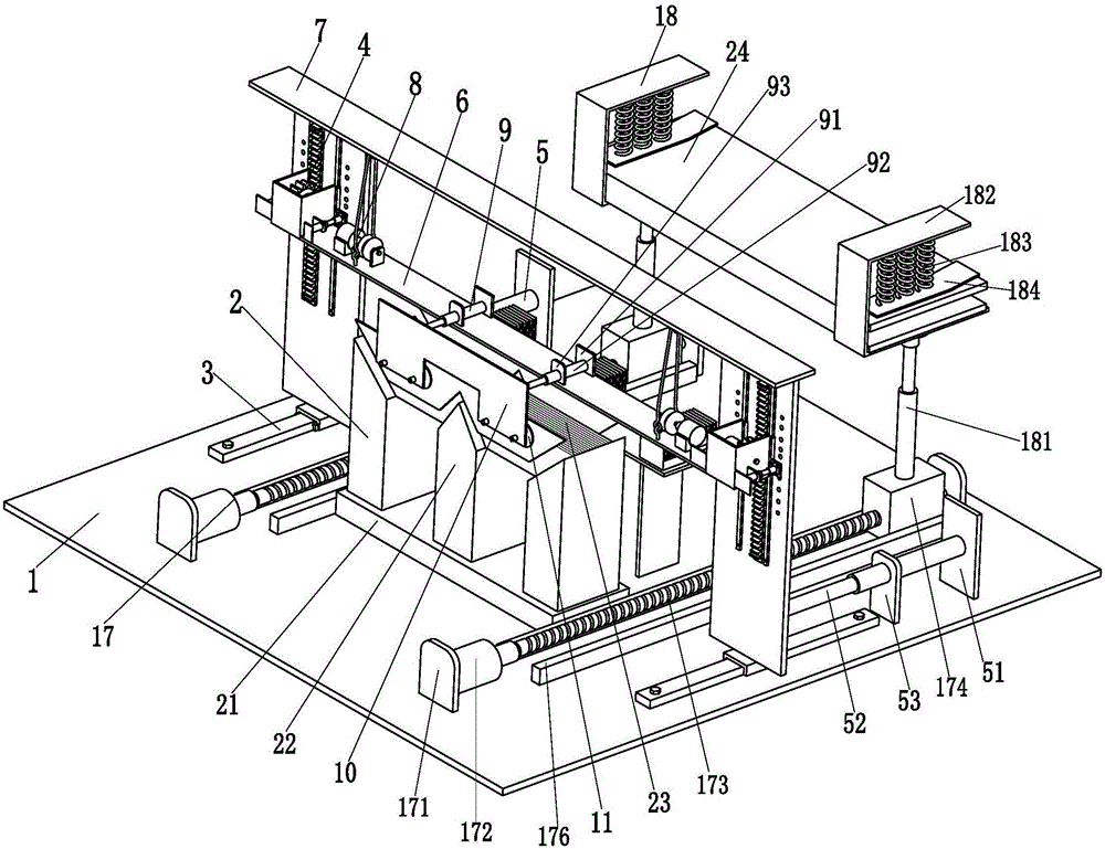
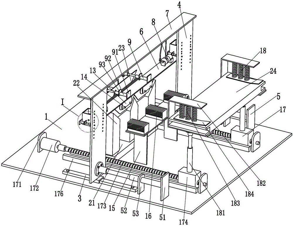
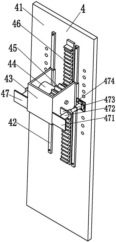
[0032] Such as Figure 1 to Figure 7 As shown, a distribution network transformer manufacturing equipment containing a three-phase three-column iron core includes a base plate 1 and an iron core 2 placed on the upper end face of the base plate 1. The type of the iron core 2 is a three-phase three-column iron core in the present invention. core, the iron core 2 is composed of a lower iron 21 placed on the bottom plate 1, three core columns 22 evenly installed on the lower iron 21, an upper iron 22 placed on the three core columns 22, and an upper iron installed on the upper iron The upper clamping piece 23 is composed of a plurality of iron plates 24. Two No. 1 linear slide rails 3 are symmetrically installed on the upper end surface of the base ...


PUM


Abstract

The invention relates to power distribution network transformer manufacturing equipment with a three-phase three-column iron core. The equipment comprises a bottom plate and the iron core mounted on the upper end surface of the bottom plate. The iron core comprises a lower iron yoke, three core columns, an upper iron yoke and an upper clamping part, the three core columns are uniformly mounted on the lower iron yoke, the upper iron yoke is mounted on the three core columns, and the upper clamping part is mounted on the upper yoke and formed by a plurality of iron yoke pieces. Two first linear slide rails are symmetrically mounted on the upper end face of the bottom plate, a lifting mechanism is mounted on each first linear slide rail, a moving mechanism is mounted on the lower back of each lifting mechanism and arranged on the bottom plate, and each lifting mechanism is driven to move back and forth by the corresponding moving mechanism. A lifting plate is mounted between the two lifting mechanisms of the two first linear slide rails, a frame plate is mounted at top ends of the two lifting mechanisms, and two auxiliary driving mechanisms are symmetrically mounted between the frame plate and the lifting plate. The power distribution network transformer manufacturing equipment with the three-phase three-column iron core can realize an automatic rapid transformer manufacturing function.

Description

technical field [0001] The invention relates to the technical field of transformer processing, in particular to a manufacturing equipment for a distribution network transformer containing a three-phase three-column iron core. Background technique [0002] The transformer uses the principle of electromagnetic induction to change the AC voltage. It has the functions of voltage conversion, current conversion, impedance conversion, isolation and voltage stabilization. Therefore, it is widely used in distribution network substations. The transformer is composed of a coil and an iron core. The core is mainly composed of the lower clamp, the lower iron core, the core column, the upper iron core and the upper clamp. The manufacturing process of the transformer is as follows: the first step is to manually remove the upper clamp of the iron core; the second step is that the operator Slowly take and remove the upper iron pieces in turn; the third step, the operator sets the lower end i...

Claims


Application Information

Patent Timeline
IPC IPC(8): H01F41/00B66F19/00B23P19/00
CPCB23P19/00B66F19/00B66F2700/03B66F2700/09H01F41/00
Inventor 储德姣
Owner 江苏凡高电气有限公司
Learn More