Jig disassembling equipment

A jig and equipment technology, applied in metal processing equipment, manufacturing tools, metal processing and other directions, can solve the problems of low fixture disassembly and clamping efficiency, manual injury, high labor cost, and achieve automatic disassembly, improve disassembly efficiency, Realize the effect of automatic cutting

Pending Publication Date: 2021-02-02
DONGGUAN WORLD PRECISION MACHINERY
View PDF0 Cites 3 Cited by
  • Summary
  • Abstract
  • Description
  • Claims
  • Application Information

AI Technical Summary

Problems solved by technology

However, at present, manual disassembly and assembly is adopted for the disassembly and assembly of fixtures, which has low efficiency of disassembly and assembly of fixtures, high labor costs and easy to cause manual injury.

Method used


Image

  • Jig disassembling equipment
  • Jig disassembling equipment
  • Jig disassembling equipment

Examples


Embodiment Construction

[0026]In order to describe the technical content and structural features of the present invention in detail, the following will further explain in conjunction with the embodiments and the accompanying drawings.

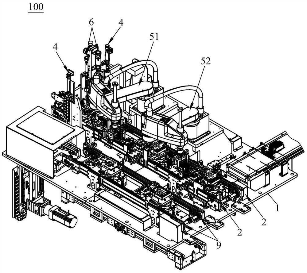
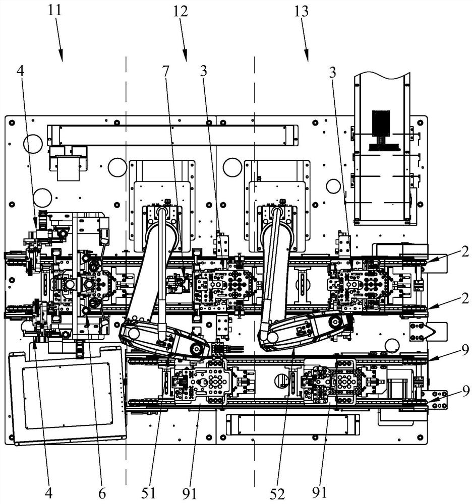
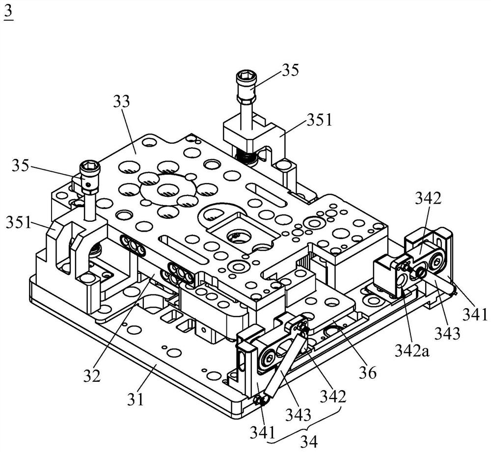
[0027]SeeFigure 1 to Figure 4 , The jig disassembly equipment 100 of the present invention includes a frame 1, a first conveying line 2, a jig 3, a platen opening mechanism 4, a first manipulator 51 and a second manipulator 52, and the first conveying line 2 is set on the frame 1. , The frame 1 is sequentially provided with a first station 11, a second station 12 and a third station 13 along the conveying direction of the first conveying line 2; the jig 3 is placed on the first conveying line 2, and the first conveying line 2 The jig 3 can be transported to the first station 11, the second station 12 and the third station 13 in sequence. The jig 3 includes the jig bottom plate 31, the jig limit middle frame 32, the jig upper cover 33 and The elastic pressing assembly 34, the f...


PUM


Abstract

The invention provides jig disassembling equipment. The jig disassembling equipment comprises a rack, first conveying lines, jigs, pressing plate opening mechanisms, a first manipulator and a second manipulator, wherein the rack is sequentially provided with a first station, a second station and a third station in the conveying direction of the first conveying lines; the jigs are placed on the first conveying lines and comprise jig bottom plates, jig limiting middle frames, jig upper covers and elastic pressing assemblies, the jig bottom plates are provided with placement stations for allowingradiators to be placed, the jig limiting middle frames are detachably stacked in the jig bottom plates, and the jig upper covers cover the jig limiting middle frames and are detachably stacked on thejig bottom plates, and the elastic pressing assemblies comprise first supporting seats, rotary pressing plates and first elastic pieces; the pressing plate opening mechanisms are arranged on the rackand located at the first station, and the pressing plate opening mechanisms can drive the rotary pressing plates to rotate to be disengaged from the jig upper covers; and the first manipulator is used for disassembling the jig upper covers, and the second manipulator is used for disassembling the jig limiting middle frames and taking out the radiators located on the jig bottom plates.

Description

Technical field[0001]The invention relates to the field of radiator processing, in particular to a fixture disassembly device for disassembling a fixture for clamping a radiator.Background technique[0002]In the existing process of component processing of the radiator of an electronic product, the parts of the radiator are often welded together by welding, that is, the metal parts are welded together through a high soldering tin. In order to improve processing efficiency, reflow soldering is often used to assemble and solder the radiator. When assembling and welding, first place the parts of the radiator in the matching fixture, and then send the fixture and the parts into the reflow soldering furnace for the furnace to complete the assembly. Before and after the furnace, the fixture needs to be disassembled and clamped. However, in the prior art, a manual disassembly and assembly method is adopted for the disassembly and assembly of the clamp, and the disassembly and assembly of the...

Claims


Application Information

Patent Timeline
Patent Type & Authority Applications(China)
IPC IPC(8): B23P21/00B23P19/027B23P19/00
CPCB23P19/001B23P19/002B23P19/007B23P19/027B23P21/004
Inventor 张华礼邓春华周成超李颖香
Owner DONGGUAN WORLD PRECISION MACHINERY
Why Eureka
Try Eureka