Wall-embedded type pipe box and installation method thereof
What is Al technical title?
Al technical title is built by PatSnap Al team. It summarizes the technical point description of the patent document.
A duct box and wall-embedded technology
Pending Publication Date: 2018-12-07
彭士城
View PDF0 Cites 1 Cited by
Summary
Abstract
Description
Claims
Application Information
AI Technical Summary
This helps you quickly interpret patents by identifying the three key elements:
Problems solved by technology
Method used
Benefits of technology
Problems solved by technology
There are two types of installation methods for horizontal branch pipes: surface installation and concealed installation. Surface installation means that the pipe is directly installed on the outer surface of the wall. Although it is convenient for installation and maintenance, it affects the appearance of the interior. This installation method is generally used to improve the appearance of the building interior. Low-end residential buildings with low requirements; concealed installation is to make grooves in the wall, and the pipes are directly buried in the wall. This installation method does not affect the indoor appearance, but once the pipe joint leaks or the water pressure is too high, the pipe bursts Water leakage, or indoor hot water pipe aging and water seepage, often only when you find water seepage through the gaps in the floor tiles or damp and moldy walls, can you know that there is a problem with the pipes in the wall, and you can’t know exactly where the pipes are leaking, so you have to cut all the walls look up
The wall chiseling construction not only affects the normal use of the bathroom and kitchen, but also brings construction dust and noise, which affects the living environment and brings great inconvenience to life
Method used
Image
Click on the blue label to locate the original text in one second.
Reading with bidirectional positioning of images and text.
Examples
Embodiment 1
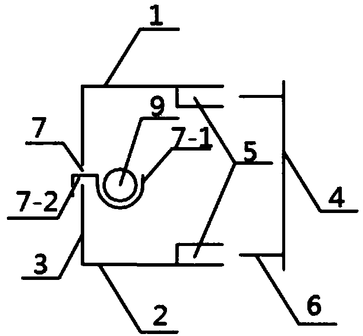
[0043] Such as Figure 1~2 As shown, this embodiment provides a wall-mounted duct box, including a box body and a movable cover 4, the box body includes an upper panel 1 and a lower panel 2, the rear end of the upper panel 1 and the rear end of the lower panel 2 pass through a The vertical panel 3 is connected; the box body is used to be embedded in the wall, and the movable cover plate 4 is used to be detachably installed on the front end of the box body and flush with the wall body; the inner surface of the vertical panel 3 is also provided with one or One or more pipe clamps used to secure the pipe.
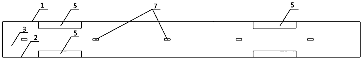
[0044] Further, as figure 1 , 2 , 7, the front end of the inner surface of the upper panel 1 and the front end of the inner surface of the lower panel 2 are provided with grooves 5, and the upper and lower ends of the inner surface of the movable cover 4 are respectively provided with a protrusion 6 that matches the groove 5 . In this specific embodiment, the positions of ...
Embodiment 2
[0057] Such as image 3 As shown, this embodiment provides a wall-mounted pipe box for simultaneously installing two pipes 9 to be installed, the tap water pipe and the hot water pipe. The difference between this embodiment and the first embodiment is only the pipe collar on the vertical panel The number of rows of installation seams 7 is different, and the number of pipe collars is different. The installation steps, usage methods and technical effects of other wall-mounted duct boxes are the same as those in Embodiment 1, and will not be repeated here.
Embodiment 3
[0059] Such as Figure 4~5 As shown, this embodiment provides a wall-mounted duct box, including a box body and a movable cover 4, the box body includes an upper panel 1 and a lower panel 2, the rear end of the upper panel 1 and the rear end of the lower panel 2 pass through a The vertical panel 3 is connected; the box body is used to be embedded in the wall, and the movable cover plate 4 is used to be detachably installed on the front end of the box body and flush with the wall body; the inner surface of the vertical panel 3 is also provided with one or One or more pipe clamps used to secure the pipe.
[0060] Further, as Figure 4 , 5 , 7, the front end of the inner surface of the upper panel 1 and the front end of the inner surface of the lower panel 2 are provided with grooves 5, and the upper and lower ends of the inner surface of the movable cover 4 are respectively provided with a protrusion 6 that matches the groove 5 . In this specific embodiment, the positions of...
PUM
Abstract
The invention discloses a wall-embedded type pipe box and relates to the field of building decoration. The pipe box includes a box body and a movable cover plate, the box body includes an upper paneland a lower panel, and the rear end of the upper panel and the rear end of the lower panel are connected with each other through a vertical panel. The box body is used for being embedded in a wall body, and the movable cover plate is used for being detachably mounted at the front end of the box body and is flush with the wall body; a pipe hoop used for fixing a pipe is also arranged on the inner side face of the vertical panel. The wall-embedded type pipe box is used for being embedded into a wall, the box body is internally provided with the pipe hoop for fixing the pipe, the movable cover plate is detachably mounted at the front end of the box body and is flush with the wall body, and when it is needed to overhaul the pipe, the movable cover plate can be detached, so that installation and overhaul are both convenient. According to a provided installation method of the wall-embedded type pipe box, the operation is simple, and by painting the movable cover plate in a color or a floralpattern same as a wall surface, not only can the indoor appearance not be influenced, but also the problems are solved that after the pipe is directly buried in the wall body, it is difficult to findout and determine damaged pipeline leakage parts and overhaul is inconvenient.
Description
technical field [0001] The invention relates to the field of building decoration, in particular to a wall-embedded duct box and an installation method thereof. Background technique [0002] Building water supply is to provide the municipal water supply pipe network to the building, directly or through the water pump pressurized by the standpipe to each floor of the building, and each floor supplies water to the toilet and kitchen from the standpipe through the horizontal branch pipe. There are two types of installation methods for horizontal branch pipes: surface installation and concealed installation. Surface installation means that the pipe is directly installed on the outer surface of the wall. Although it is convenient for installation and maintenance, it affects the appearance of the interior. This installation method is generally used to improve the appearance of the building interior. Low-end residential buildings with low requirements; concealed installation is to m...
Claims
Application Information
Patent Timeline
Application Date:The date an application was filed.
Publication Date:The date a patent or application was officially published.
First Publication Date:The earliest publication date of a patent with the same application number.
Issue Date:Publication date of the patent grant document.
PCT Entry Date:The Entry date of PCT National Phase.
Estimated Expiry Date:The statutory expiry date of a patent right according to the Patent Law, and it is the longest term of protection that the patent right can achieve without the termination of the patent right due to other reasons(Term extension factor has been taken into account ).
Invalid Date:Actual expiry date is based on effective date or publication date of legal transaction data of invalid patent.