Building automatic formwork connecting system and precise positioning system thereof

A technology for automatic and precise positioning of buildings, which is applied in the fields of construction, building structure, and on-site preparation of building components. Effect

Pending Publication Date: 2018-12-07
SHENZHEN EXCELLENCE INDZATION INTELLIGENT CONSTR DEV CO LTD
View PDF8 Cites 2 Cited by
  • Summary
  • Abstract
  • Description
  • Claims
  • Application Information

AI Technical Summary

Problems solved by technology

[0006] The purpose of the present invention is to address the deficiencies in the prior art, and provide a building automatic mold clamping system and its precise positioning system, and the use of the detection console can solve the problem of low work efficiency

Method used


Image

  • Building automatic formwork connecting system and precise positioning system thereof
  • Building automatic formwork connecting system and precise positioning system thereof
  • Building automatic formwork connecting system and precise positioning system thereof

Examples


Embodiment 1

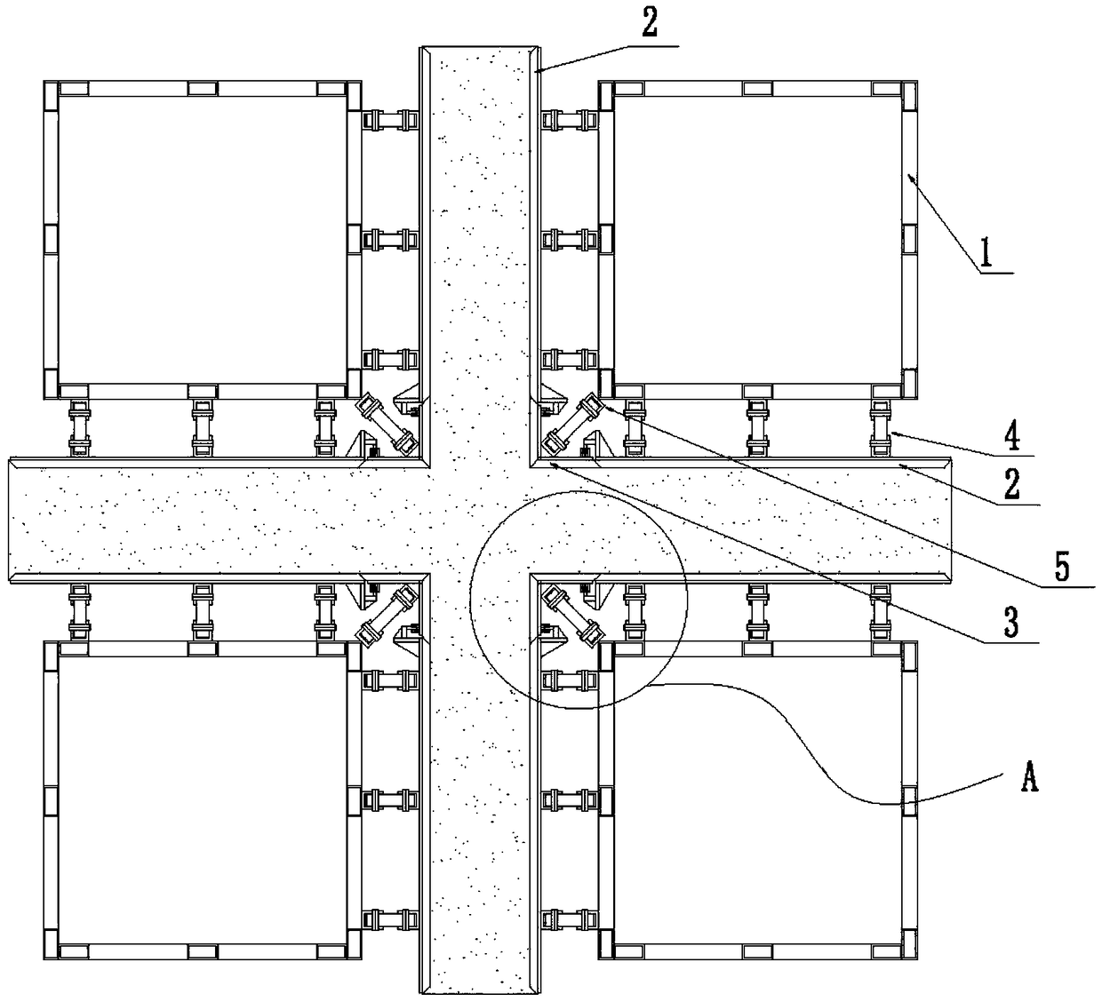
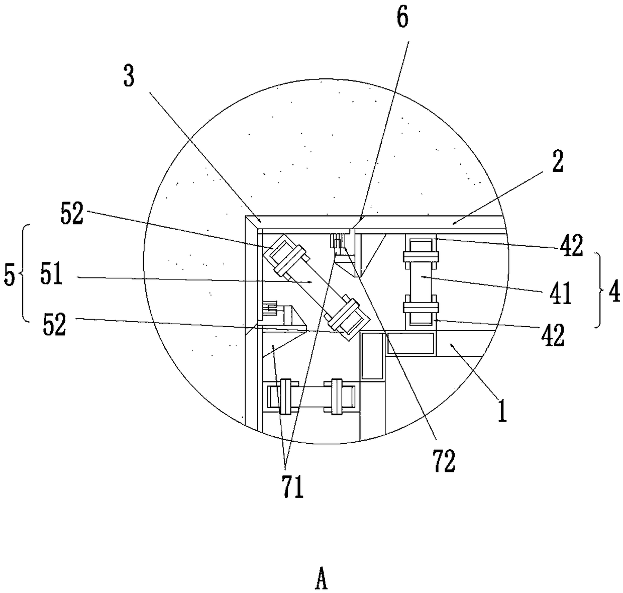
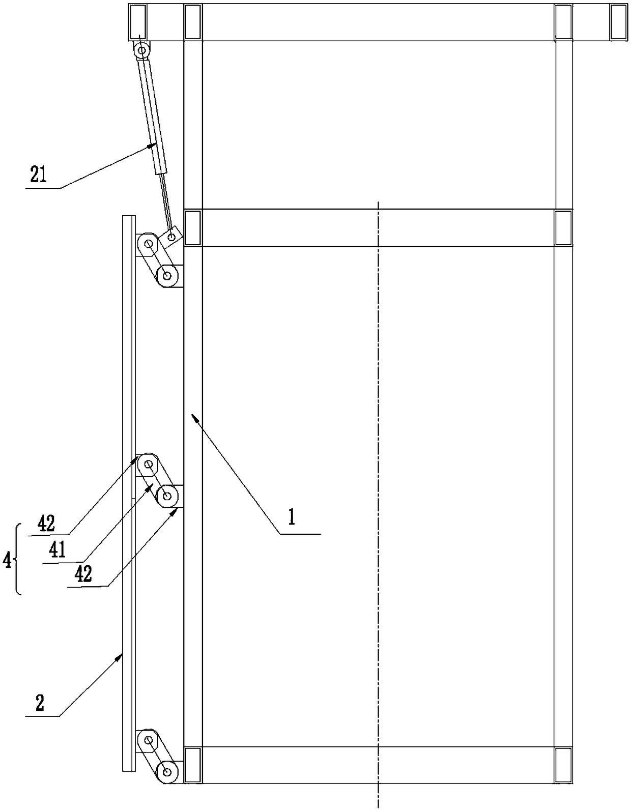
[0028] The specific implementation of the building automatic mold clamping system of the present invention, as Figure 1 to Figure 4 As shown, it includes a center frame 1, a second formwork 3, a first formwork 2 and at least two connecting rod assemblies, image 3 It is a schematic diagram of the structure of the opening and closing device in the mold opening state, Figure 4 It is a schematic diagram of the structure of the opening and closing device in the mold closing state.

[0029] please see figure 1 and figure 2 , first of all, it should be explained that in this embodiment, the first template 2 is a flat template, the second template 3 is a corner template, and the angle between the corner templates is a right angle. The above design method is mainly suitable for cross-shaped walls Or a wall with a right-angled corner, of course, both the first template 2 and the second template 3 can be flat templates, which are suitable for long flat walls, and the specific shap...

Embodiment 2

[0038] The second specific implementation mode of the building automatic mold clamping precise positioning system of the present application, such as Figure 5 As mentioned above, the main technical solutions of this embodiment are the same as those of Embodiment 1, and the features not explained in this embodiment are explained in Embodiment 1, and will not be repeated here. The difference between this embodiment and Embodiment 1 is that both the first template 2 and the second template are flat templates. Of course, it can also be set that the first template 2 is a flat template and the second template 3 is a corner template. The holder is a positioning groove 81 horizontally arranged on the back of the first template 2, and the second clamping member is a positioning block 82 horizontally arranged on the back of the second template 3. In the clamped state, the positioning block 82 is inserted into the positioning groove 81 and engaged; The notch of the positioning groove 81...


PUM


Abstract

The invention relates to the technical field of building devices, in particular to a building automatic formwork connecting system which comprises a central frame, a second formwork, a first formworkand at least two connecting rod assemblies. One end of the first connecting rod assembly is hinged to the central frame, and the other end of the first connecting rod assembly is hinged to the back side of the first formwork. One end of the second connecting rod assembly is hinged to the central frame, and the other end of the second connecting rod assembly is hinged to the back side of the secondformwork. The top end of the central frame is provided with at least two drivers with telescopic rods. The first driver is hinged to the top end of the central frame. The telescopic rod of the firstdriver is hinged to the first connecting rod assembly. In the formwork connecting state, the side face of the first formwork and the opposite side face of the second formwork are connected; compared with the prior art, by using the drivers as the power source, the work efficiency is improved, and the labor intensity of workers is relieved. The invention further provides a building automatic formwork connecting precise positioning system. By means of the system, the seamless connection between the formworks can be realized.

Description

technical field [0001] The invention relates to the technical field of construction equipment, in particular to a building automatic mold clamping system, and also to a building automatic mold clamping precise positioning system. Background technique [0002] Building formwork is needed when concrete is poured into the walls of houses in construction. The current building formwork is mainly divided into steel formwork and wood formwork. First of all, steel formwork has the advantages of high strength, high rigidity and long cycle life, but due to its heavy weight, The labor intensity of workers is high, it is inconvenient to use, and the work efficiency is low; the wooden formwork has the advantages of light weight and relatively low labor intensity of workers, but it has the problem of short service life and serious waste of wood. [0003] At present, the formwork used in building walls is mainly divided into two types, one is flat formwork, which is used for flat walls, an...

Claims


Application Information

Patent Timeline
Patent Type & Authority Applications(China)
IPC IPC(8): E04G17/00
CPCE04G17/00
Inventor 柳雪春柳黎
Owner SHENZHEN EXCELLENCE INDZATION INTELLIGENT CONSTR DEV CO LTD
Why Eureka
Try Eureka