Damping gap adjustable magnetorheological damper with series liquid flow channels

A magneto-rheological damper and liquid flow channel technology, applied in the direction of shock absorbers, shock absorbers, springs/shock absorbers, etc., can solve the problem of increasing the axial size of the piston, increasing the overall size of the damper, and reducing damping The problem of the effective working stroke of the device is solved, and the damping force adjustment range is wide, the dynamic adjustment range is wide, and the working performance is good.

Active Publication Date: 2018-12-07
EAST CHINA JIAOTONG UNIVERSITY
View PDF8 Cites 13 Cited by
  • Summary
  • Abstract
  • Description
  • Claims
  • Application Information

AI Technical Summary

Problems solved by technology

But it will also bring some disadvantages: increasing the inner diameter of the damper cylinder will lead to an increase in the overall size of the damper; changing the thickness of the damping gap requires the use of magnetorheological dampers with different structures. The thickness of the damping gap is fixed and cannot be adjusted, which is difficult to meet the application requirements under different working conditions; when the multi-stage piston structure is used to increase the damping length to increase the output damping force, the axial dimension of the piston will be increased. , will reduce the effective working stroke of the damper

Method used


Image

  • Damping gap adjustable magnetorheological damper with series liquid flow channels
  • Damping gap adjustable magnetorheological damper with series liquid flow channels
  • Damping gap adjustable magnetorheological damper with series liquid flow channels

Examples


Embodiment Construction

[0021] Below in conjunction with accompanying drawing and embodiment the present invention will be further described:

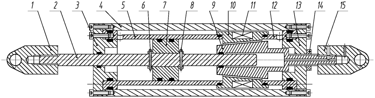
[0022] figure 1 Shown is the structure diagram of the present invention. It mainly includes: left lug 1, piston rod 2, left end cover 3, outer cylinder body 4, left inner cylinder body 5, left conical pin 6, piston head 7, right conical pin 8, valve core 9, bobbin frame 10, Exciting coil 11, right inner cylinder body 12, right end cover 13, lock nut 14 and right lifting lug 15.

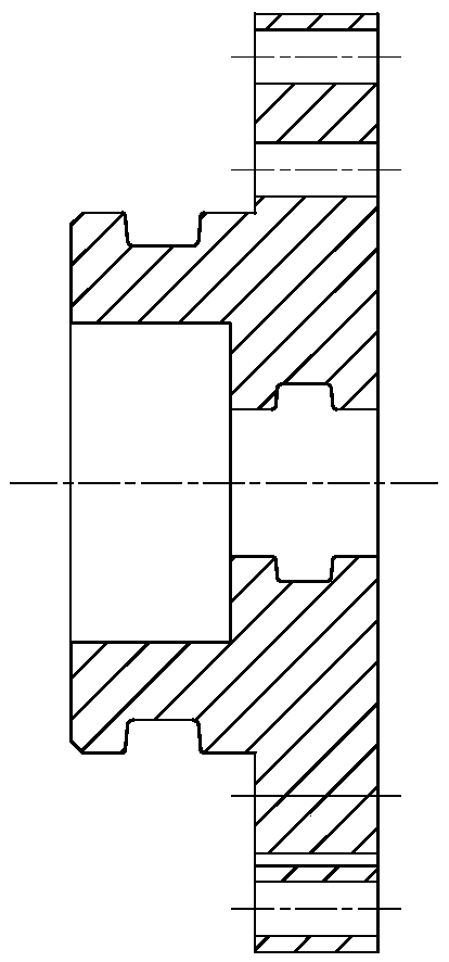
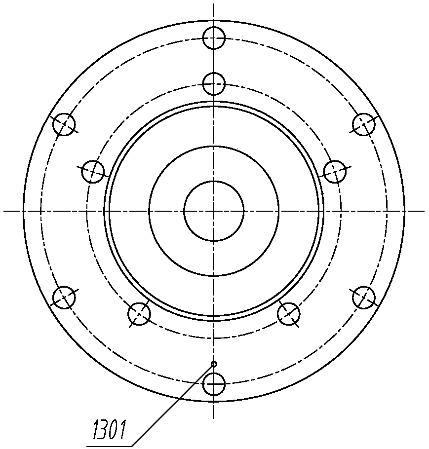
[0023] figure 2 Shown is the sectional view of the right end cover of the present invention, image 3 It is the left view of the right end cover of the present invention. The center of the right end face of the right end cover 13 is processed with a circular through hole, which can act as an axial positioning function for the left end of the piston rod 2; There are 6 threaded holes on the left end surface of the body 4, which can be used for positioning and connection with the ou...


PUM


Abstract

The invention discloses a damping gap adjustable magnetorheological damper with series liquid flow channels. The damper is mainly composed of a piston rod, an end cover, cylinder bodies, a piston head, a valve element, an excitation coil, a winding frame and the like. The conical liquid flow channel is formed in a gap between the valve element and the winding frame, the circular liquid flow channel is formed in a gap between the outer cylinder body and the winding frame, the conical liquid flow channel and the circular liquid flow channel make up a series liquid flow channel structure, and four effective damping gaps can be formed under action of a magnetic field, wherein the liquid flow channel formed between the winding frame and the valve element can form two conical effective damping gaps, the thickness of the damping gaps can be changed through adjusting the valve element position, so that the effect of adjusting damping force magnitude is achieved. When the excitation coil is powered on to work, effective control of the damping force can be realized through controlling the magnitude of current. According to the damper, liquid flow damping length is effectively increased through the series liquid flow channels, it is guaranteed that the damper can output the damping force which is strong enough and wide in adjustable range, and is particularly suitable for vibration damping systems in industries of railway, traffic and the like.

Description

technical field [0001] The invention relates to a magneto-rheological damper, in particular to a magneto-rheological damper with an adjustable damping gap having a series liquid flow channel. Background technique [0002] The characteristics of millisecond-level response speed, large control range and large damping force output of the magneto-rheological damper make it an excellent semi-active actuator in the field of industrial applications. At present, magnetorheological dampers have been widely used in vibration reduction and anti-seismic systems of buildings and bridges, and vibration reduction of railway rolling stock and automobile suspension systems. [0003] The magnetorheological damper excitation coil currently designed is usually wound in the circular groove of the piston head, and a circular liquid flow channel is set inside the piston head or a circular ring is set between the outer surface of the piston and the inner surface of the cylinder. Shaped flow channe...

Claims


Application Information

Patent Timeline
Patent Type & Authority Applications(China)
IPC IPC(8): F16F9/53F16F9/48F16F9/34
CPCF16F9/34F16F9/483F16F9/535
Inventor 胡国良邓英俊喻理梵丁孺琦
Owner EAST CHINA JIAOTONG UNIVERSITY
Why Eureka
Try Eureka