Double-rail sintering furnace mesh belt

A technology for sintering furnaces and mesh belts, applied in furnaces, furnace materials, furnace types, etc., can solve problems affecting product quality, reducing production efficiency, and white spots in the back electric field, so as to reduce chipped corners, reduce contact area, and The effect of electric field white point reduction

Pending Publication Date: 2018-12-07
SUZHOU RUNYANG PHOTOVOLTAIC TECH
View PDF6 Cites 1 Cited by
  • Summary
  • Abstract
  • Description
  • Claims
  • Application Information

AI Technical Summary

Problems solved by technology

[0003] At present, in the existing sintering furnace mesh belt, the thimbles are arranged at equal intervals without inclination angles, so that the surface of the thimbles is easily ground out of grooves, and the cells are stuck on both sides of the thimbles that are ground out of the gap, resulting in silicon peeling, missing corners or Fragments, and the place where the thimble is ground will touch the back electric field of the cell. After the contact part is sintered in the sintering furnace, due to uneven heating, white spots appear on the back electric field after sintering. At the same time, the fixing direction of the thimble is perpendicular to the mesh belt body and Arranged at equal intervals, when the cells are transported to the mesh belt, the chamfers of the cells are prone to be inserted into the ejector pins, resulting in debris, which not only reduces the production efficiency, but also affects the quality of the product

Method used


Image

  • Double-rail sintering furnace mesh belt
  • Double-rail sintering furnace mesh belt

Examples


Embodiment Construction

[0013] The following description serves to disclose the present invention to enable those skilled in the art to carry out the present invention. The preferred embodiments described below are only examples, and those skilled in the art can devise other obvious variations. The basic principles of the present invention defined in the following description can be applied to other embodiments, variations, improvements, equivalents and other technical solutions without departing from the spirit and scope of the present invention.

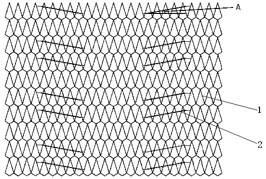
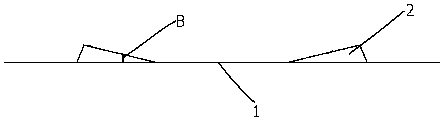
[0014] see figure 1 , is a structural diagram of the mesh belt and thimble of one of the tracks on the double-track sintering furnace. As shown in the figure, the double-track sintering furnace (not shown) in this embodiment is equipped with a first track (not shown) and a second track Track (not shown), the first track and the second track are respectively provided with a mesh belt, and the mesh belt on the first track is used as an example to illustrat...


PUM


Abstract

The invention relates to the technical field of solar cell piece production, and particularly provides a double-rail sintering furnace mesh belt. A double-rail sintering furnace is provided with a first rail and a second rail, the mesh belt is arranged on each of the first rail and the second rail, wherein each mesh belt comprises a mesh belt body, a plurality of ejector pins are arranged on eachmesh belt body, every two ejector pins form an ejector pin pair, the ejector pin pairs are arranged in the length directions of the mesh belt bodies in a left-right symmetry mode, and an included angle is formed between the bottom surface of each ejector pin and the horizontal direction of the corresponding mesh belt body. The probability that the chamfer of a cell piece is inserted into each ejector pin is reduced, the probability of clamping breaking and corner missing caused by the mesh belt ejector pins is reduced, meanwhile, the contact area between the cell piece and the corresponding ejector pin is reduced, and finally, the white points of the back electric field after the cell piece is sintered are reduced.

Description

technical field [0001] The invention belongs to the technical field of solar cell production, and in particular relates to a double-track sintering furnace mesh belt. Background technique [0002] A sintering furnace mesh belt is involved in the existing cell production process. After the crystalline silicon solar cell is screen-printed, it is generally transported to the sintering furnace by a mesh belt for the sintering operation, so that the crystal The silicon cell and the printed electrode form a good ohmic contact, thus forming the positive and negative electrodes of the solar cell, and the mesh belt circulates inside and outside the sintering furnace through the transmission shaft. [0003] At present, in the existing sintering furnace mesh belt, the thimbles are arranged at equal intervals without inclination angles, so that the surface of the thimbles is easily ground out of grooves, and the cells are stuck on both sides of the thimbles that are ground out of the ga...

Claims


Application Information

Patent Timeline
Patent Type & Authority Applications(China)
IPC IPC(8): F27B9/30F27B9/24F27B9/38
CPCF27B9/24F27B9/30F27B9/38F27M2003/04F27B2009/382
Inventor 王强
Owner SUZHOU RUNYANG PHOTOVOLTAIC TECH
Why Eureka
Try Eureka