Measurement method of magnetic levitation thermobalance based on photothermal rapid temperature rise

A measurement method and magnetic levitation technology, applied in the direction of weighing by removing a certain component, can solve the problems of slow heating rate, complex equipment structure, affecting measurement accuracy, etc., and achieve the effect of precise temperature control

Active Publication Date: 2020-07-14
HUAZHONG UNIV OF SCI & TECH
View PDF5 Cites 0 Cited by
  • Summary
  • Abstract
  • Description
  • Claims
  • Application Information

AI Technical Summary

Problems solved by technology

However, this mechanical thermobalance is increasingly unable to meet the complex experimental conditions of high temperature, high heating rate, high pressure, and corrosive atmosphere in modern analysis and testing.
[0004] The Chinese patent with the application number CN200620127972.8 discloses a high-temperature thermobalance, which adopts the simplest structure of hanging and connecting the balance sample in the vertical tube resistance furnace, and does not consider the influence of air flow and temperature on the thermobalance measurement
The Chinese patent with the application number CN200910243952.5 discloses a method for controlling reaction gas channeling of a thermobalance analyzer and a pressurized thermobalance analyzer, in which an isolator is added on the basis of the former to prevent reaction gas channeling, but the equipment The structure is complex, and the balance and the reactant are in the same chamber, which will affect the measurement accuracy and application range to a certain extent
The Chinese patent with the application number CN201010104591.9 discloses a controllable rapid heating thermobalance reaction furnace. The sample is pushed into the sample through the lifting device to achieve rapid heating. The unknown actual heating rate and the vibration during the lifting process will affect the measurement results.
The Chinese patent with the application number CN201010590839.7 discloses a thermobalance with a controllable high heating rate, which uses a double-layer metal wire mesh to heat the material through the wire mesh reaction system, and the heating rate can reach up to 1000°C / s. The inevitable change of heat flux from cold state to hot state and the hysteresis of the temperature adjustment effect caused by heat retention put forward very high requirements for the temperature control of the thermobalance in this heating mode.
The Chinese patent with the application number CN201210501784.7 discloses a microwave heating quality detection device, which uses microwave heating to rapidly heat materials. However, different materials absorb microwaves very differently, making it difficult to control the heating rate. Thermobalances are suitable Weaker
[0005] Among the existing commercial products, whether it is a normal-pressure thermobalance or a high-pressure thermobalance, the traditional electric furnace heating method is still used, and the fastest heating rate is only 50-100K / min. The mechanically connected balance measurement method makes the pressure and atmosphere of the test have received a lot of restrictions, but also produced a large system error, affecting the measurement accuracy
[0006] The magnetic levitation thermogravimetric analyzer of Rubotherm in Germany adopts a pull-down magnetic levitation system, which makes thermogravimetric analysis possible under UHV and corrosive atmospheres. However, it still uses the traditional thermal balance measurement method of converting the displacement of the external stator end into electricity. , the zero adjustment under different working conditions is very slow, and the disturbance in the measurement process will also generate much more noise than the traditional mechanical connection method. Analyzer Applications

Method used


Image

  • Measurement method of magnetic levitation thermobalance based on photothermal rapid temperature rise
  • Measurement method of magnetic levitation thermobalance based on photothermal rapid temperature rise
  • Measurement method of magnetic levitation thermobalance based on photothermal rapid temperature rise

Examples


Embodiment 1

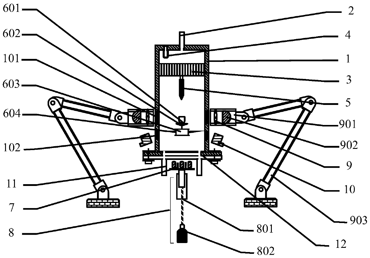
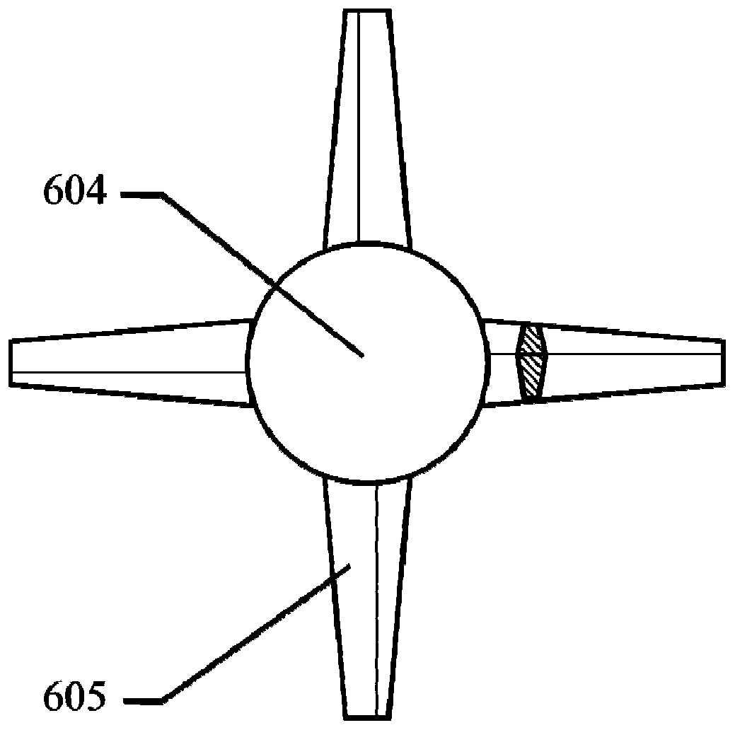
[0057] Such as Figure 1~5 As shown, this embodiment discloses a magnetic levitation thermal balance based on photothermal rapid temperature rise specially designed for realizing the method of the present invention, which includes a closed container 1, a reaction pool 601, a magnetic levitation device, a stator lifting assembly 8, and a laser displacement monitoring Component 10, photothermal heating component 9 and photothermal heating component displacement device 903, wherein:

[0058] The airtight container 1 is cylindrical, with a gas inlet 2 at the center of the top end, and a detachable cover plate 12 (fixed by bolts) at the lower end. Two gas outlets 11 are symmetrically arranged on the cover plate 12. The airtight container 1 The interior is provided with a pressure monitoring component 4, an airflow stabilizing device 3, and an infrared temperature measuring component 5, and the side wall is provided with a displacement monitoring window 102 made of a transparent mat...

Embodiment 2

[0066] This embodiment discloses a method for measuring the quality change of materials under temperature control conditions using the magnetic levitation thermobalance in Embodiment 1, and the steps are as follows:

[0067] 1) Weigh the mass as g 0 The measured materials are sent to the reaction pool 601;

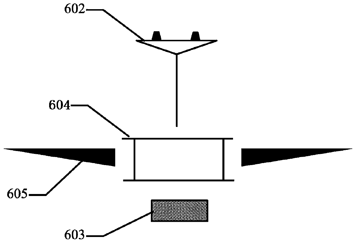
[0068] 2) Remove the cover plate 12, place the reaction pool 601 on the support frame 602 of the magnetic levitation float 603, then place the magnetic levitation float 603 on the center of the cover plate 12, install the cover plate 12 on the airtight container 1, and adjust the magnetic levitation stator 7 The position makes it be located directly below the center of the rear cover plate 12 after installation;

[0069] 3) Start the magnetic levitation device, and after the magnetic field is stable, move the magnetic levitation stator 7 upwards, so that the magnetic levitation float 603 is suspended in the airtight container 1;

[0070] 4) Continuously feed the gas need...

Embodiment 3

[0084] This embodiment discloses the method for establishing a database using multiple groups of controlled experiments, and the specific steps are as follows:

[0085] 1) Determine the mass range of the thermobalance according to the needs of the experiment. Within this range, select the initial mass g at equidistant distances 0 , recorded as g from the minimum value to the maximum value 01 ,..., g 0i ,..., g 0m , i is an integer, and 1

[0086] 2) Determine the range of gas flow velocity according to the needs of the experiment. Within this range, select the calibration flow velocity v equidistantly, and record it as v in sequence from the minimum value to the maximum value 1 ,...,v j ,...,v n , j is an integer, and 1

[0087] 3) Take a set of v j , g 0i , use another analytical balance to weigh the mass as g 0i The measured material is put into the reaction tank, and then the reaction tank is placed in the thermal balance, and the magnetic levitation floa...


PUM


Abstract

The invention discloses a magnetic suspension thermobalance measurement method based on rapid photothermal heating. The method comprises the following steps: 1) weighing and taking a measurement material into a reaction tank; 2) placing the reaction tank into a closed container together with a magnetic suspension float; 3) suspending a magnetic suspension float in the closed container by a magnetic suspension device; 4) introducing a gas into the closed container; 5) measuring the real-time position of the magnetic suspension float by a laser displacement monitoring assembly, and adjusting theposition of a magnetic suspension stator to suspend the magnetic suspension float to a measurement zero position; 6) heating the reaction tank by photothermal heating assemblies; 7) adjusting the positions of the photothermal heating assemblies to maintain a heating beam on the reaction tank; 8) measuring the temperature of the measurement material in the reaction tank; and 9) recording the displacement of the magnetic suspension float, and converting the displacement into mass. The displacement of the magnetic suspension float is measured, and is converted into material mass change, so the systematic error is reduced, and high-precision measurement of the material mass change under a temperature control condition is achieved.

Description

technical field [0001] The invention relates to a measurement method of a magnetic levitation thermal balance, in particular to a measurement method of a magnetic levitation thermal balance based on rapid temperature rise of light and heat. Background technique [0002] Thermogravimetric analysis refers to a thermal analysis technique that measures the relationship between the mass of the sample to be tested and the temperature change under program-controlled temperature, and is used to study the thermal stability and composition of materials. The most important instrument used in thermogravimetric analysis is a thermobalance. [0003] The traditional thermal balance adopts a mechanical structure, which is mainly composed of a recording balance, a balance heating furnace, a program temperature control system and a recorder. Among them, the basic principle of the recording balance is to convert the balance displacement caused by the change of sample quality into electric qua...

Claims


Application Information

Patent Timeline
Patent Type & Authority Patents(China)
IPC IPC(8): G01N5/04
CPCG01N5/04
Inventor 胡松李寒剑池寰瀛向军苏胜汪一许凯邓增通何立模徐俊韩亨达
Owner HUAZHONG UNIV OF SCI & TECH
Why Eureka
Try Eureka