Micropressure permeameter, and test method thereof

A test method and technology of permeameters, which are applied in the field of permeameters, can solve the problems of difficult accurate measurement of flow rates and slow water flow in low-permeability media, and achieve the effect of avoiding errors

Inactive Publication Date: 2018-12-07
INST OF HYDROGEOLOGY & ENVIRONMENTAL GEOLOGY CHINESE ACAD OF GEOLOGICAL SCI
View PDF8 Cites 3 Cited by
  • Summary
  • Abstract
  • Description
  • Claims
  • Application Information

AI Technical Summary

Problems solved by technology

[0006] In view of the above problems, the technical problem to be solved by the present invention is to provide a micro-pressure osmometer...

Method used


Image

  • Micropressure permeameter, and test method thereof
  • Micropressure permeameter, and test method thereof
  • Micropressure permeameter, and test method thereof

Examples


preparation example Construction

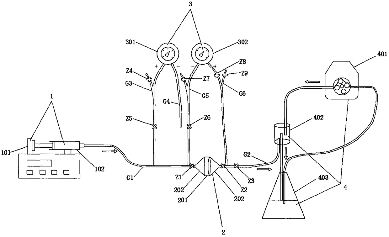
[0018] Step 1. Preparation of the sample. If it is the undisturbed soil, first use a utility knife to trim it into a cylindrical soil sample slightly higher than the ring knife, then press the special ring knife 201 into the soil sample, use the utility knife to flatten the top, and cover it Funnel-type sand core 202; then turn the soil sample together with the funnel-type sand core 202 vertically 180 degrees, continue to use a utility knife to flatten the other side of the ring knife, cover another funnel-type sand core 202, and finally fix the funnel with two duckbill clips Around the sand core 202, if it is remolding soil, first place the special ring knife 201 on the funnel-type sand core 202, fill the remolding soil to the top of the special ring knife 201, and cover another funnel-type sand core 202, Finally, use a duckbill clip to fix the surroundings of the funnel-type sand core;

[0019] Step 2. The sample is saturated with water. Inject a certain amount of liquid, pu...

Embodiment

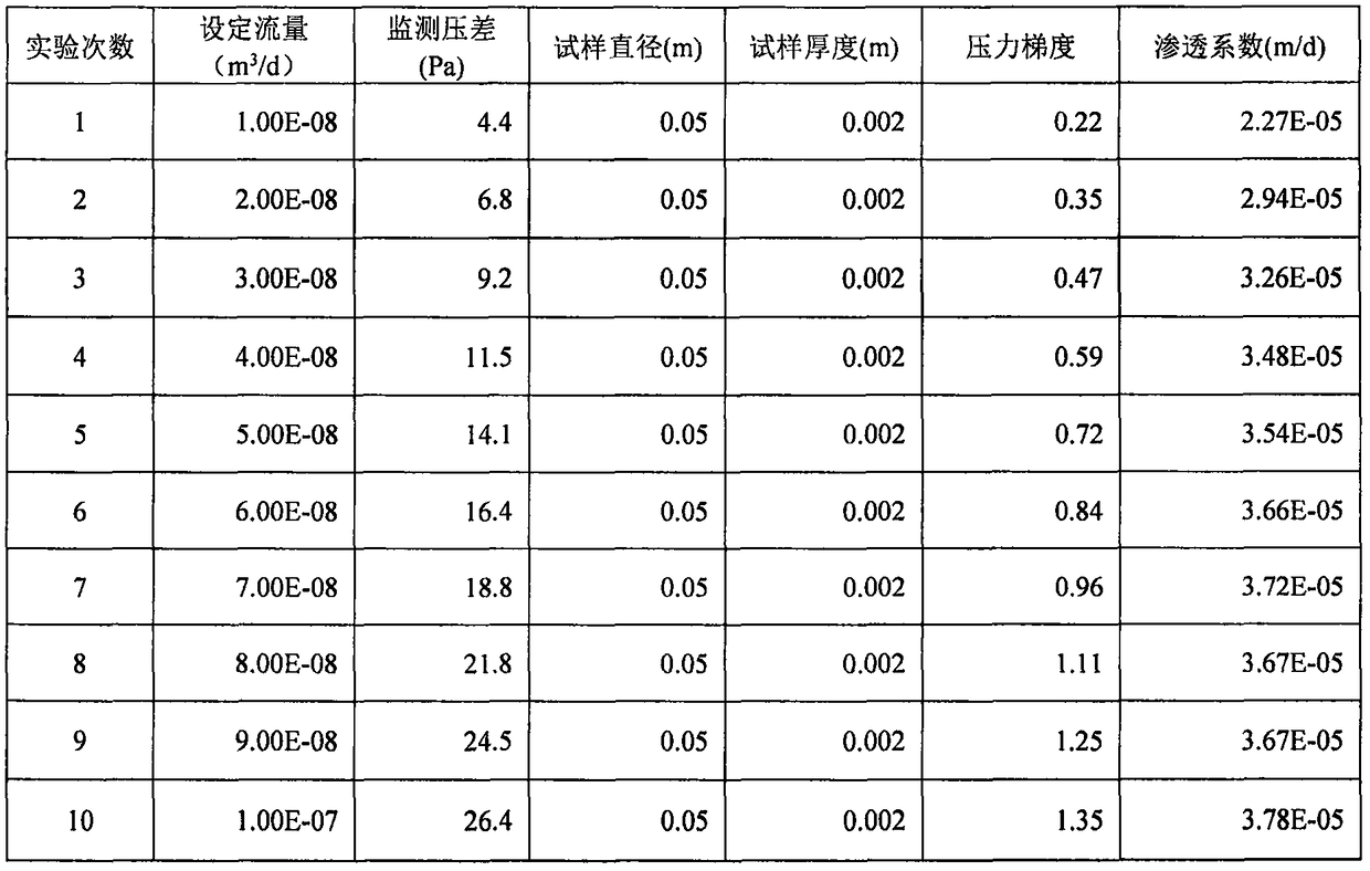
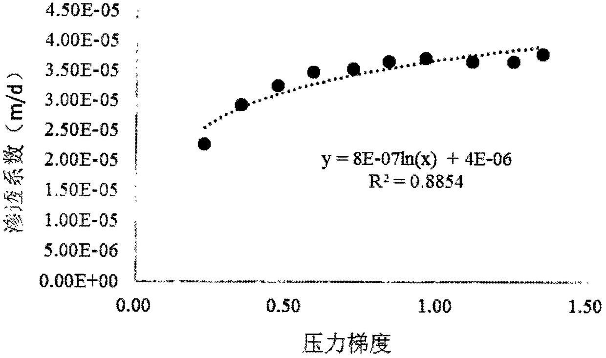
[0033] Embodiment: The test process of the undisturbed soil and the remolded soil is exactly the same, but the sample preparation process is slightly different. The test data of an undisturbed soil is used to illustrate how to realize the calculation of permeability coefficient and the establishment of mathematical equations. Prepare samples according to step 1; saturate the sample according to step 2; adjust the water level at the water inlet and outlet according to step 3. According to step four, to figure 2 The flow rate set in the first experiment is 1.00E-08m 3 / d Inject fluid. According to step 5, monitor the value change of the differential pressure gauge. After the value is stable, record the reading of the second differential pressure gauge to figure 2 (4.4Pa), according to figure 2 Repeat step 4 and step 5 10 times at the flow rate set in , and record the pressure difference after each experiment stabilizes at the same time. After the 10 experiments are compl...


PUM

PropertyMeasurementUnit
Thicknessaaaaaaaaaa

Abstract

The invention discloses a micropressure permeameter, and a test method thereof, and belongs to the technical field of permeameter. According to the micropressure permeameter, a water inlet module is composed of a micro-injection pump and a microsyringe, and is used for accurate controlling of low speed flow amount; a sample cabin is composed of a specially produced cutting ring and two tunnel-shaped sand cores, and is used for accommodating samples; a pressure gradient monitoring module is composed of a first micro differential pressure gauge and a second micro differential pressure gauge, andis used for monitoring pressure change; a discharged water level control module is mainly composed of a peristaltic pump, a filter cup, and a conical flask. The test method comprises following steps:1, sample preparation; 2, sample water saturation; 3, water level leveling; and 4, flow body injection. The principle of the micropressure permeameter is different from that in the prior art that a water level is set firstly, and flow amount is monitored, so that error in measuring process of a flowmeter is avoided. The micro differential pressure gauges are used for monitoring the small pressuredifference between a water inlet end and a water outlet end, measuring of the penetration coefficients under extremely low pressure gradient conditions can be realized. The thin type cutting ring used for accommodating soil samples is specially designed, so that requirements of different mediums are satisfied.

Description

Technical field: [0001] The invention relates to a micro-pressure osmometer and a testing method, belonging to the technical field of osmometers. Background technique: [0002] Permeameter is the most important method to test the permeability coefficient of porous media. Conventional permeameters mostly use water level control devices to control the water pressure at both ends of the sample, and use Darcy's law to calculate the permeability coefficient according to the flow rate monitored at the water outlet. For cohesive soil with low permeability, etc., due to the small flow rate under normal pressure, the method of increasing the pressure gradient is often used to measure the permeability coefficient. [0003] Due to the poor permeability of cohesive soil and other media, the pressure gradient controlled by the atmospheric pressure permeameter is relatively small, and the amount of water passing through the sample per unit time is very small. In addition, there are exter...

Claims


Application Information

Patent Timeline
IPC IPC(8): G01N15/08
CPCG01N15/0826
Inventor 郝奇琛魏士禹张翼龙朱玉晨陆川
Owner INST OF HYDROGEOLOGY & ENVIRONMENTAL GEOLOGY CHINESE ACAD OF GEOLOGICAL SCI
Why Eureka
Try Eureka