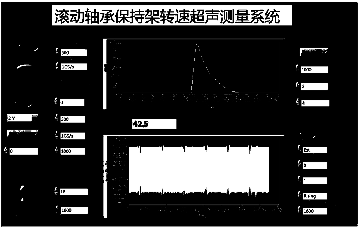
Ultrasonic-wave-based measuring system and method for rotation speed of bearing holding rack

A bearing cage and measuring system technology, applied in the field of bearing cage rotational speed measurement system, can solve the problems of increased bearing wear, early failure, probe and roller collision, etc., to improve measurement accuracy, stable and reliable operation, and improve repeatability. The effect of frequency

Inactive Publication Date: 2018-12-07
XI AN JIAOTONG UNIV
View PDF11 Cites 5 Cited by
  • Summary
  • Abstract
  • Description
  • Claims
  • Application Information

AI Technical Summary

Problems solved by technology

The slipping phenomenon that occurs during the operation of high-speed rolling bearings will cause the wear and early failure of the bearing inner and outer ring raceways and rolling element surfaces, which will have a great impact on the normal operation of rolling bearings, thus seriously threatening the safe operation of aero-engines
[0004] The traditional methods of measuring the speed of the cage include optical method, electromagnetic method, eddy current method, stress method, etc. During optical measurement, under high temperature and high speed conditions, the oil mist in the bearing will block the optical path; during electromagnetic measurement, the magnetic field will It leads to the combination of grinding debris in the bearing, which leads to aggravated wear of the bearing; the measurement range of the eddy current method is narrow, and it may cause collision between the probe and the roller at high speed; the stress method is easily affected by vibration, and the above measurement methods are limited by their own shortcomings. , are not suitable for bearing cage speed measurement in industrial sites and high speed conditions

Method used


Image

  • Ultrasonic-wave-based measuring system and method for rotation speed of bearing holding rack
  • Ultrasonic-wave-based measuring system and method for rotation speed of bearing holding rack
  • Ultrasonic-wave-based measuring system and method for rotation speed of bearing holding rack

Examples


Embodiment Construction

[0031] The present invention will be described in detail below in conjunction with the accompanying drawings and specific embodiments.

[0032] In describing the present invention, it should be understood that the terms "center", "longitudinal", "transverse", "upper", "lower", "front", "rear", "left", "right", " The orientations or positional relationships indicated by "vertical", "horizontal", "top", "bottom", "inner" and "outer" are based on the orientations or positional relationships shown in the drawings, and are only for the convenience of describing the present invention and Simplified descriptions, rather than indicating or implying that the device or element referred to must have a particular orientation, be constructed and operate in a particular orientation, and thus should not be construed as limiting the invention. In addition, the terms "first" and "second" are used for descriptive purposes only, and cannot be understood as indicating or implying relative importa...


PUM


Abstract

The invention discloses an ultrasonic-wave-based measuring system and method for the rotation speed of a bearing holding rack. The ultrasonic-wave-based measuring system comprises a computer, an ultrasonic probe, a dual-channel high-frequency ultrasonic probe transmitting and receiving board, and a two-channel virtual oscilloscope. The ultrasonic probe transmitting and receiving board excites theultrasonic probe and receives an echo signal from the ultrasonic probe; the two-channel virtual oscilloscope carries out collection in real time; and the rotating speed is calculated in real time by the computer. Therefore, Real-time measurement of the rotating speed of the holding rack is realized. After verification, the system can work stably and reliably; and the design requirement is met.

Description

technical field [0001] The invention belongs to the technical field of bearing speed measurement and running state detection, and in particular relates to a measurement system and method for the speed of a bearing cage based on ultrasonic waves. Background technique [0002] The bearing rotor system is the core component of the rotary machine, responsible for the transmission of power and torque, and also the main factor for the safety, high efficiency, precision and stable operation of the equipment. The dynamic performance of the rotor system is directly related to its supporting bearings. Cylindrical rollers, as a typical line contact pair, have the advantages of large radial load capacity and small friction coefficient, and are widely used in large rotating machinery. [0003] Rolling bearings used in the aerospace field generally have a high speed, and the working environment is relatively harsh, and the performance requirements for the rolling bearings are relatively h...

Claims


Application Information

Patent Timeline
Patent Type & Authority Applications(China)
IPC IPC(8): G01P3/00
CPCG01P3/00
Inventor 刘恒李丁成李猛王琦刘意田桂斌
Owner XI AN JIAOTONG UNIV
Why Eureka
Try Eureka