Linear motor test platform

A test platform, linear motor technology, applied in the direction of motor generator testing, measuring devices, force/torque/work measuring instruments, etc., can solve the problems of low running speed, maximum thrust limit, difficult structure simplification, etc., to improve safety , improve the compatibility, the effect of simplified structure

Active Publication Date: 2018-12-07
GUANGZHOU HAOZHI ELECTROMECHANICAL
View PDF18 Cites 7 Cited by
  • Summary
  • Abstract
  • Description
  • Claims
  • Application Information

AI Technical Summary

Problems solved by technology

[0006] Existing linear motor test benches usually use high-precision servo motors + couplings + lead screws for motor thrust testing. However, test benches that use lead screws for motor force measurement have obvious shortcomings in terms of test speed.
Usually, due to the speed limitation of the servo motor (usually no more than 6000RPM) and the lead limitation of the screw, the speed of the screw drive is often much lower than that of the linear motor.
Therefore, when the servo motor has reached the limit speed, the linear motor has not yet reached the rated speed, which makes the screw force measurement scheme unable to be tested at the rated speed of the linear motor
This means that the thrust of the motor at this speed can only be estimated using other parameters, which brings inconvenience and error to the test of the motor
[0007] 2. There are hidden dangers in the test
Out of control is a serious hidden danger in the operation of the entire system
[0009] 3. Low test accuracy
[0011] 4. The structure is not easy to simplify
Compared with the lead screw solution, the test accuracy of this solution is greatly improved. However, the drag motor itself also has thrust fluctuations, maximum speed limits, and maximum thrust limits. These conditions will still bring troubles to the test of the motor under test.

Method used


Image

  • Linear motor test platform
  • Linear motor test platform
  • Linear motor test platform

Examples


Embodiment Construction

[0039] In the following, the present invention will be further described in conjunction with the drawings and specific implementations. It should be noted that, provided that there is no conflict, the following embodiments or technical features can be combined to form new embodiments. .

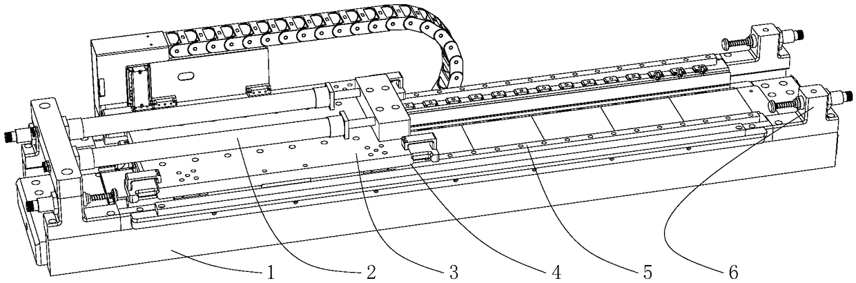
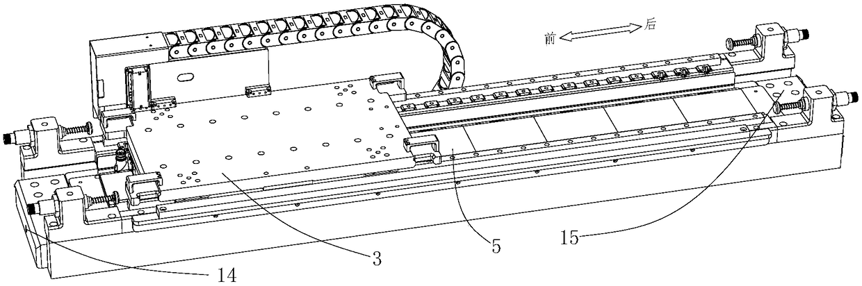
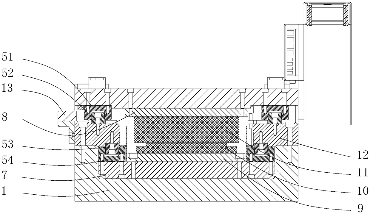
[0040] Such as Figure 1-9 A linear motor test platform shown includes a bed 1, a linear track 5, a test platform 4, a grating ruler 13, a pre-tensioning mechanism 14 and a force measuring mechanism 15. The linear track 5 is set on the bed 1, and the test platform 4 Located on the linear track 5, the test platform 4 and the linear track 5 are movably connected. The test platform 4 is formed with an accommodation chamber for accommodating the linear motor under test. The test platform 4 is used to connect with the linear motor under test. The measuring linear motor drives the test platform 4 to move on the linear track 5. The grating ruler 13 is located on one side of the test platform 4, and th...


PUM


Abstract

The invention discloses a linear motor test platform which comprises a bed body, a linear track, a test platform, a grating ruler, a pre-tightening mechanism and a force measuring mechanism. The linear track is arranged on the bed body, the test platform and the linear track are connected in a movable manner, a receiving chamber is formed on the test platform, the test platform is connected to a linear motor to be tested, the test platform is driven by the linear motor to be tested to move on the linear track, the grating ruler is positioned on one side of the test platform, the grating ruleris connected with the bed body, the pre-tightening mechanism and the force measuring force mechanism are respectively positioned on two ends of the bed body, the pre-tightening mechanism and the forcemeasuring mechanism are connected with the test platform, the pre-tightening mechanism is used for reducing frictional interference that the testing platform suffers from, and the force measuring mechanism is used for measuring thrust force of the linear motor to be tested. The linear motor test platform is concise in structure and high in compatibility with different types of linear motors; testsafety is improved, a phenomenon that the speed of the linear motor is out of control can be prevented, a situation of collision can be prevented, and test accuracy can be improved.

Description

Technical field [0001] The invention relates to a motor testing technology, in particular to a linear motor testing platform. Background technique [0002] The linear motor can be regarded as a rotating motor that is sectioned in the radial direction and expanded into a straight line. The stator of the rotating motor becomes the primary (also called mover) of the linear motor, and the rotor of the rotating motor becomes the secondary of the linear motor (also called the stator) . Rotary motors output torque, and linear motors output thrust. The emergence of linear motors makes reciprocating motion no longer need to be realized by complex screw rotation. At the same time, its high speed, large thrust, and small size have become the first choice for high-speed and high-precision linear feed systems. Nowadays, linear motors are more and more widely used in industrial machinery such as machining centers, electrical discharge machines and gantry systems. [0003] The design and produ...

Claims


Application Information

Patent Timeline
Patent Type & Authority Applications(China)
IPC IPC(8): G01R31/34G01L5/12
CPCG01L5/12G01R31/34
Inventor 侯宗毅钟添明汤秀清
Owner GUANGZHOU HAOZHI ELECTROMECHANICAL
Why Eureka
Try Eureka