Hot-pressing hydrocarbon-generating simulation kettle

A hydrocarbon generation simulation and reaction kettle technology, applied in teaching models, educational tools, instruments, etc., can solve the problems of inconvenient leak detection and maintenance, bulky equipment, etc., to achieve leak detection and maintenance, high efficiency and speed fast effect

Active Publication Date: 2018-12-07
CHINA PETROLEUM & CHEM CORP +1
6 Cites 6 Cited by

AI-Extracted Technical Summary

Problems solved by technology

[0003] The invention provides a hot-pressed hydrocarbon generation simulation tank with different acquisition parameters, whi...

Method used

Because the direction of motion of above-mentioned outer piston rod 123 and inner piston rod 122 is identical, all is upward movement and pressure is applied to reactor 107, therefore makes the speed of operation and detection faster, more efficient, and more conducive to Leak detection and maintenance; in addition, since the two move in the same direction, the inner piston rod 122 can be arranged inside the outer piston rod 123 to reduce the volume of the entire device.
Further, reactor 107 is structured as an internal hollow columnar structure, wherein the hollow interior can directly place rock sample 111, cancels the sample chamber in the existing device, makes reactor 107 internal structure simple, loads and unloads sa...

Abstract

The invention relates to a hot-pressing hydrocarbon-generating simulation kettle, which relates to the technical field of simulation experiment devices, and is used for solving the technical problemsthat the equipment existing in the prior art is bulky and inconvenient in leak detection and maintenance. The hot-pressing hydrocarbon-generating simulation kettle comprises a reaction kettle used foraccommodating a rock sample, wherein one end of the reaction kettle is provided with an outer piston rod and an inner piston rod. Since the inner piston rod and the outer piston rod move in the samedirection, namely, the inner piston rod and the outer piston rod apply pressure to the reaction kettle in the same direction, so that the operation and detection speed is faster and the efficiency ishigher, thereby being more conductive to leak detection and maintenance. In addition, since the inner piston rod is arranged inside the outer piston rod, the entire hot-pressing hydrocarbon-generatingsimulation kettle can be more miniaturized.

Application Domain

Educational models

Technology Topic

EngineeringHot press +5

Image

  • Hot-pressing hydrocarbon-generating simulation kettle
  • Hot-pressing hydrocarbon-generating simulation kettle
  • Hot-pressing hydrocarbon-generating simulation kettle

Examples

  • Experimental program(1)

Example Embodiment

[0040] The present invention will be further described below in conjunction with the drawings.
[0041] In the description of the present invention, it should be understood that the directions or positional relationships indicated by the terms "upper", "lower", "front", "rear", "inner", and "outer" are based on the drawings shown The orientation or positional relationship is only for the convenience of describing the present invention and simplifying the description, rather than indicating or implying that the pointed device or element must have a specific orientation, be constructed and operated in a specific orientation, and therefore cannot be understood as a limitation of the present invention.
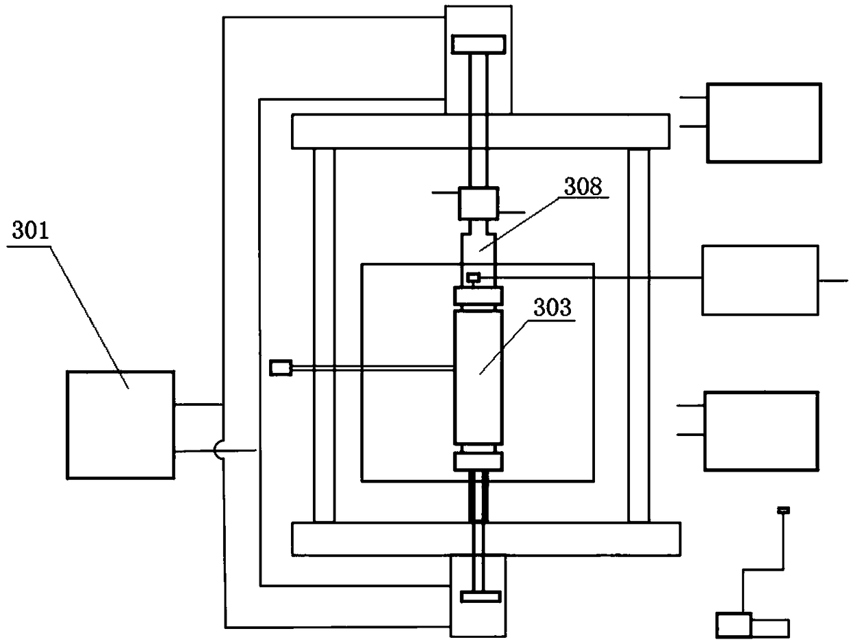
[0042] image 3 It is a flow chart of a hot-pressed hydrocarbon generation simulation reactor in the embodiment of the present invention; image 3 As shown, the present invention provides a hot-pressing hydrocarbon generation simulation reactor with different acquisition parameters, which is mainly used for geochemical simulation experiment research in the field of petroleum and natural gas. It includes a reaction vessel 107 for placing the rock sample 111. One end of the reaction vessel 107 is provided with an outer piston rod 123 and an inner piston rod 122. The inner piston rod 122 is arranged inside the outer piston rod 123 and the axes of the two coincide with each other. The movement directions of the piston rod 122 and the outer piston rod 123 are the same.
[0043] In one embodiment, the reaction kettle 107 is placed vertically, the outer piston rod 123 is located below the reaction kettle 107, and the inner piston rod 122 is located inside the outer piston rod 123. The outer piston rod 123 can move upward and apply upward pressure to the reaction kettle 107. At the same time, the inner piston rod 122 also moves upward and exerts upward pressure on the reactor 107. This pressure can act on the rock sample 111 inside the reactor 107 to cause it to react.
[0044] Since the above-mentioned outer piston rod 123 and inner piston rod 122 move in the same direction, they both move upward and press the reactor 107, so the operation and detection speed is faster, the efficiency is higher, and it is more conducive to leak detection and Maintenance; In addition, because the two moving directions are the same, the inner piston rod 122 can be arranged inside the outer piston rod 123, which can reduce the volume of the entire device.
[0045] The sealing method of the outer piston rod 123 on the lower end of the reactor 107 is as follows:
[0046] A seal assembly 15 is provided on the reactor 107 near the port of the outer piston rod 123, and a connector assembly 16 is provided between the seal assembly 15 and the outer piston rod 123. The outer piston rod 123 is used to integrate the connector. The pressure is applied at 16 and the reactor 107 is sealed.
[0047] Such as Figure 5 As shown, the connector assembly 16 includes a T-shaped compression sleeve 117, a second compression ring 118, a second ceramic heat insulation sleeve 119, and a heat dissipation mandrel 121 that are connected in sequence. The T-shaped compression sleeve 117 is connected to the seal assembly 15. The heat dissipation top rod 121 is connected to the end of the outer piston rod 123.
[0048] Such as Figure 4 As shown, the seal assembly 15 includes a reactor sealing ring 113, a graphite sealing ring 114, and a copper sealing ring 115 arranged in sequence; the copper sealing ring 115 is provided with a recess 14 and a T-shaped pressure sleeve 117 is provided with a protrusion 13. The raised portion 13 is arranged in the recessed portion 14.
[0049] When the outer piston rod 123 moves upwards, an upward force is applied to the heat dissipation top rod 121, and the force is transmitted to the seal assembly 15 through the second ceramic heat insulation sleeve 119, the second pressure ring 118 and the T-shaped pressure sleeve 117 , The red copper sealing ring 115, the graphite sealing ring 114 and the reaction kettle sealing ring 113 are all deformed, and the lower port of the reaction kettle 107 can be axially self-tightening dynamic sealing. After the sealing is completed, it can be ensured that the reactor 107 can withstand the formation fluid pressure of up to 180 MPa without leakage.
[0050] Among them, the second ceramic heat insulation sleeve 119 can not only play the role of heat resistance and heat insulation, but also does not affect the transmission of axial force, ensuring that the rock sample 111 is evenly heated.
[0051] Such as Figure 5 As shown, a plurality of heat dissipation ribs are provided on the outer wall of the heat dissipation mandrel 121 to make the heat dissipate more quickly and prevent the outer piston rod 123 from being thermally damaged.
[0052] The sealing method of the outer piston rod 123 on the upper end of the reactor 107 is as follows:
[0053] Such as Figure 4 As shown, the reaction vessel 107 is provided with a porous sintered plate 105 and a rock sample end cover 104 in sequence at a port away from the outer piston rod 123, and a V-shaped copper seal ring 106 is also set between the rock sample end cover 104 and the reaction vessel 107.
[0054] Furthermore, the porous sintered plate 105 is located inside the upper end of the reactor 107 and is used to seal the chamber in the reactor 107 where the rock sample 111 is placed.
[0055] Further, a V-shaped groove is opened on the upper end surface of the reaction kettle 107, and the V-shaped copper seal ring 106 is arranged in the V-shaped groove.
[0056] Further, the lower end of the rock sample end cover 104 is provided with a pressing part, which extends into the reactor 107 and contacts the upper surface of the porous sintered plate 105, and the lower end of the rock sample end cover 104 is also provided with a V-shaped insert The V-shaped insertion part is located outside the pressing part, and the V-shaped insertion part is arranged in the opening at the upper end of the V-shaped copper seal ring 106.
[0057] When the outer piston rod 123 moves upwards, an upward force is applied to the connecting piece assembly 16, which is transmitted to the reactor 107 through the seal assembly 15, and the reactor 107 generates a reaction force, which causes the V-shaped copper seal ring 106 to deform. , The upper port of the reactor 107 can be statically sealed.
[0058] At this point, through the upward movement of the piston rod 123, the sealing of the reactor 107 can be completed.
[0059] The internal piston rod 122 applies pressure to the reactor 107 in the following manner:
[0060] Such as Figure 4 with 5 As shown, the inside of the reactor 107 is provided with a metal filter 112 for fixing the rock sample 111, the end of the inner piston rod 122 is provided with a rock sample jack 116, and the rock sample jack 116 passes through the connector assembly 16 and The seal assembly 15 is also connected to the metal filter 112.
[0061] A ceramic heat insulation pad 120 is provided between the inner piston rod 122 and the rock sample top rod 116. Among them, the ceramic heat insulation pad 120 not only plays a role of heat and heat insulation, but also does not affect the transmission of axial force, ensuring that the rock sample 111 is evenly heated.
[0062] When the inner piston rod 122 moves upward, the ceramic heat insulation pad 120, the rock sample jack 116, and the metal filter 112 are sequentially pushed to generate upward displacement, thereby applying static rock pressure and confining pressure to the rock sample 111.
[0063] Furthermore, the reactor 107 is constructed as a hollow cylindrical structure, and the rock sample 111 can be directly placed inside the hollow interior, eliminating the sample chamber in the existing device, making the reactor 107 simple in internal structure, quick to load and unload samples, and easy to operate. ; And it avoids the phenomenon of seizure of the internal parts of the reactor under high temperature and high pressure.
[0064] In one embodiment, the rock sample end cover 104 is provided with a first liquid discharge port 103 communicating with the inside of the reaction vessel 107, and the first liquid discharge port 103 is connected to the reaction vessel 107 through the opening on the rock sample end cover 104 The inside is connected, and the sample end cover 104 is provided with a valve for controlling sampling. When the valve is opened, the hydrocarbon expulsion product generated in the reactor 107 can be collected through the first liquid discharge port 103.
[0065] In addition, the reaction vessel 107 is also provided with a second liquid discharge port 109, and the second liquid discharge port 109 is communicated with the inside of the reaction vessel 107 through a porous filter column 110. Such as figure 1 As shown, the second liquid discharge port 109 is located on the side of the reactor 107, and a control valve is provided on the second liquid discharge port 109. High pressure fluid can be injected according to experimental requirements, and the hydrocarbon expulsion products generated in the reactor 107 can also be collected .
[0066] In one embodiment, the hot-pressing hydrocarbon generation simulation reactor with different acquisition parameters provided by the present invention further includes a gantry 10 and a hydraulic device 124. The gantry 10 includes a first beam 17 and a second beam 18, and a one-way hydraulic control device 124 and The second beam 18 is fixedly connected, and the one-way hydraulic control device 124 is respectively connected with the inner piston rod 122 and the outer piston rod 123; the rock sample end cover 104 is sequentially provided with a first pressure ring 102, a first ceramic heat insulation sleeve 101 and a positioning The top pillar 11 is connected to the first cross beam 17.
[0067] Among them, the first ceramic heat insulation sleeve 101 can not only play the role of heat resistance and heat insulation, but also does not affect the transmission of axial force, ensuring that the rock sample 111 is evenly heated.
[0068] The reaction vessel 107 is fixed between the first beam 17 and the second beam 18 of the gantry 10, and the reaction vessel 107 is positioned through the first ceramic heat insulation sleeve 101 and the first pressure ring 102, and a reaction force is generated. The reactor 107 is sealed.
[0069] The one-way hydraulic control device 124 can respectively control the inner piston rod 122 and the outer piston rod 123 to control different pressures.
[0070] In one embodiment, the reaction kettle 107 is installed in the box heating furnace 12; the reaction kettle 107 is provided with a kettle body temperature measuring connector 108.
[0071] Such as Image 6 As shown, the upper and lower ends of the box heating furnace 120 are respectively provided with an upper through hole 125 and a lower through hole 126. The upper through hole 125 is embedded with a first pressure ring 102 and an upper ceramic insulation sleeve 101, wherein the first The outer surface of the pressure ring 102 is provided with a positioning groove for installation and positioning; the lower through hole 126 is provided with a lower pressure ring 118, a ceramic heat insulation pad 120, a second ceramic heat insulation sleeve 119 and a heat dissipation top rod 121, respectively. The outer side of the second pressure ring 118 is also provided with a positioning groove for installation and positioning, and the reaction kettle 107 can be easily installed and unloaded through the upper through hole 125 and the lower through hole 126.
[0072] The use method of the hot-pressing hydrocarbon generation simulation kettle provided by the present invention is:
[0073] In the first step, the outer piston rod 123 is driven by the one-way hydraulic control device 124 to form an upward driving force (about 0Mpa~120MPa), and the generated force is transferred to the T-shaped pressure sleeve 117 and makes the reactor sealing ring 113 and graphite The seal ring 114 and the red copper seal ring 115 are deformed to perform a self-tightening dynamic seal on the lower port of the reactor 107. At the same time, the upward force is transferred to the rock sample end cover 104 through the positioning of the upper part of the gantry 10 to resist the reaction force 11 The V-shaped copper sealing ring 106 is deformed, and the upper port of the reaction kettle 107 is statically sealed.
[0074] In the second step, high pressure fluid (fluid pressure of 120Mpa) is injected into the reactor 107 through the lower drain port 109. During the process of injecting the liquid, the pressure changes are constantly observed to ensure that the reactor 107 is kept sealed and leak-free.
[0075] In the third step, the one-way hydraulic control device 124 drives the inner piston rod 122 to press upwards, and sequentially pushes the ceramic heat insulation pad 120 and the ejector rod 116 to generate static rock pressure and confining pressure on the rock sample 111;
[0076] The fourth step is to turn on the box heating furnace 120 to heat the reaction kettle 107 according to the temperature set by the experimental conditions, and the thermocouple is inserted into the kettle body temperature measuring connector 108 to control the temperature of the reaction kettle 107.
[0077] The invention is mainly used in the research of geochemical simulation experiments in the field of petroleum and natural gas.
[0078] Although the present invention has been described with reference to the preferred embodiments, without departing from the scope of the present invention, various modifications can be made thereto and the components therein can be replaced with equivalents. In particular, as long as there is no structural conflict, the various technical features mentioned in the various embodiments can be combined in any manner. The present invention is not limited to the specific embodiments disclosed in the text, but includes all technical solutions falling within the scope of the claims.

PUM

no PUM

Description & Claims & Application Information

We can also present the details of the Description, Claims and Application information to help users get a comprehensive understanding of the technical details of the patent, such as background art, summary of invention, brief description of drawings, description of embodiments, and other original content. On the other hand, users can also determine the specific scope of protection of the technology through the list of claims; as well as understand the changes in the life cycle of the technology with the presentation of the patent timeline. Login to view more.

Similar technology patents

Method for measuring particle size distribution of particles, and apparatus thereof

InactiveCN103983546Aacceleratelower requirement
Owner:INST OF HIGH ENERGY PHYSICS CHINESE ACADEMY OF SCI

Current based open-circuit fault detection method for three-phase inverter

InactiveCN104597368AThe overall calculation is smallaccelerate
Owner:UNIV OF ELECTRONIC SCI & TECH OF CHINA

Concrete building block cutting device

Owner:ZHEJIANG DADONGWU GROUP CONSTR OF THE NEW MATERIAL

Classification and recommendation of technical efficacy words

  • accelerate
  • Improve efficiency

Three-dimensional circuit manufacturing process and composite components of laser plastic material and manufacturing method

ActiveCN101859613Aaccelerateaccelerated continuous motion
Owner:深圳市微航磁电技术有限公司

Failure recognition method and system based on neural network self-learning

ActiveCN103914735ASpeed ​​up fault identificationaccelerate
Owner:BEIJING TAILEDE INFORMATION TECH
Why Eureka
Try Eureka