Method for controlling pre-charge state of electric vehicle

A control method and technology for electric vehicles, applied in the direction of motor control, control system, electrical components, etc., can solve the problems that the precharge resistor is not suitable for the next precharge, the precharge time is long, and the ambient temperature of the precharge resistor is high. Improve precharge efficiency, reduce precharge times, and improve precharge efficiency

Active Publication Date: 2018-12-07
SAIC MOTOR
View PDF6 Cites 5 Cited by
  • Summary
  • Abstract
  • Description
  • Claims
  • Application Information

AI Technical Summary

Problems solved by technology

[0003] The invention patent application with the Chinese patent publication number CN106314169A discloses a high-voltage pre-charge control method, system and electric vehicle. This patent application only considers the difference between the voltage difference of the load circuit and the voltage of the battery system, and does not include Taking into account the pre-charging resistance, the pre-charging resistance may not be suitable for the next pre-charging due to the long pre-charging time or the large number of current pre-charging times. At this time, if the pre-charging efficiency is low and it may burn out Precharge resistance
[0004] The invention patent application with the Chinese patent publication number CN106602622A discloses a pre-charging control method and system for electric vehicles. This patent application considers the predicted temperature of the pre-charging resistor and the load voltage of the circuit, and can judge whether the pre-charging resistor is suitable for the next time. Precharge, but the temperature of the precharge resistor is greatly affected by the ambient temperature, which cannot accurately reflect the state of the precharge resistor last precharge

Method used


Image

  • Method for controlling pre-charge state of electric vehicle
  • Method for controlling pre-charge state of electric vehicle
  • Method for controlling pre-charge state of electric vehicle

Examples


Embodiment Construction

[0041] The present invention will be further described below in conjunction with the accompanying drawings and specific embodiments.

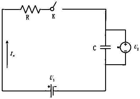
[0042] Please see attached figure 1 , a method for controlling the pre-charging state of an electric vehicle, including a pre-charging resistor R, a pre-charging relay K, a motor film capacitor C, and a battery system voltage U 1 , pre-charging resistor R, pre-charging relay K, motor film capacitor C, battery system voltage U 1 Connected as a pre-charging circuit, the load circuit voltage U 2 is the real-time voltage value across the film capacitor C of the motor.

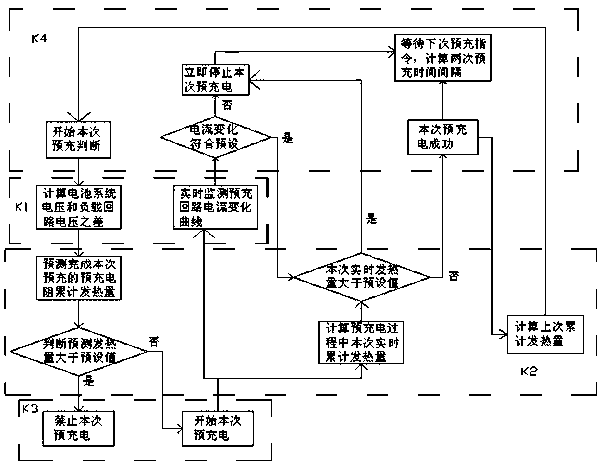
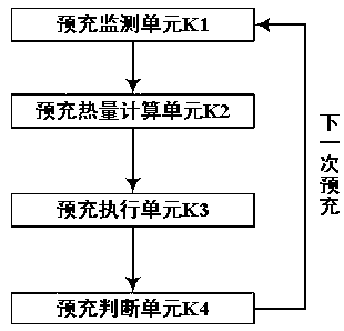
[0043] Please see attached figure 2 and attached image 3 , the method includes the following steps:

[0044] Step 1: Before the start of pre-charging, the pre-charging judging unit K4 judges whether the pre-charging condition is satisfied, and then executes step 2 after the pre-charging condition is met, otherwise, no action is taken.

[0045] Step 2: The pre-charge monitori...


PUM


Abstract

The invention discloses a method for controlling the pre-charge state of an electric vehicle. The method comprises the steps of (1) determining whether a pre-charge condition is satisfied or not, (2)calculating a difference between a battery system voltage and a load circuit voltage, (3) calculating the accumulated calorific value of a pre-charge resistor after the completion of the pre-charge, not allowing the pre-charge if the accumulated calorific value is greater than a preset calorific value, otherwise, allowing the pre-charge, (4) performing the pre-charge or prohibiting the pre-charge,(5) calculating a real-time total calorific value of the pre-charge resistor in a pre-charge process, stopping the pre-charge if the real-time total calorific value is larger than a pre-charge presetcalorific value, otherwise, continuing the pre-charge, (6) waiting for a next pre-charge command, calculating a time interval between two times of pre-charge, and (7) calculating an accumulated calorific value of a last time. According to the method, a loop load voltage and the calorific value of the pre-charge resistor are used as conditions for allowing pre-charge, the pre-charge efficiency ofthe electric vehicle can be improved, and the service life of a pre-charge loop component is prolonged.

Description

technical field [0001] The invention relates to the field of charging management of electric vehicles, in particular to a method for controlling the pre-charging state of electric vehicles. Background technique [0002] Pre-charging management is an essential and important link in new energy vehicles. The main function of electric vehicle pre-charging is to charge the large capacitor of the motor controller (that is, the inverter), so as to reduce spark arcing when the contactor contacts, and reduce the Shock for added safety. [0003] The invention patent application with the Chinese patent publication number CN106314169A discloses a high-voltage pre-charge control method, system and electric vehicle. This patent application only considers the difference between the voltage difference of the load circuit and the voltage of the battery system, and does not include Taking into account the pre-charging resistance, the pre-charging resistance may not be suitable for the next p...

Claims


Application Information

Patent Timeline
Patent Type & Authority Applications(China)
IPC IPC(8): H02P29/00
CPCH02P29/00
Inventor 张志运石泉耿以才刘晓义丁笑颜晨星
Owner SAIC MOTOR
Why Eureka
Try Eureka