Curve surface attaching clamp and attaching method

A technology for laminating jigs and fixtures, applied in chemical instruments and methods, layered products, lamination devices, etc., can solve the problems of insufficient air bubbles, affecting product quality, poor laminating effect, etc., and achieve good laminating effect , avoid the effect of not being able to fit, and improve product yield

Pending Publication Date: 2018-12-11
TRULY OPTO ELECTRONICS
View PDF0 Cites 3 Cited by
  • Summary
  • Abstract
  • Description
  • Claims
  • Application Information

AI Technical Summary

Problems solved by technology

Using the existing curved surface lamination fixture and lamination method, because the lower fixture is an integrated design, the lower fixture rises as a whole during lamination, and air bubbles are likely to be generated between the curved surface touch screen and the curved display screen, even if the pressure is continued after

Method used


Image

  • Curve surface attaching clamp and attaching method
  • Curve surface attaching clamp and attaching method

Examples


Example Embodiment

[0025] Example 1

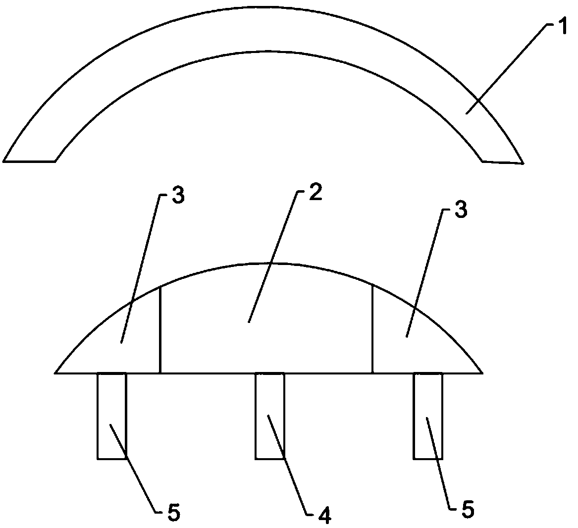
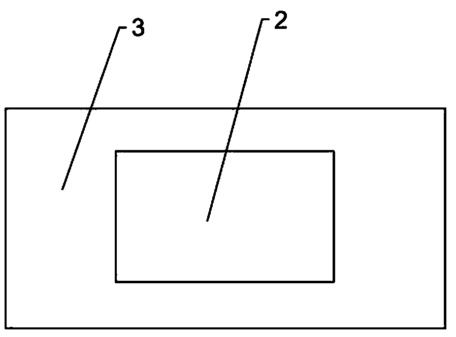
[0026] A curved surface fitting fixture, comprising an upper fixture and a lower fixture located directly below the upper fixture, the upper fixture is used for fixing a curved touch screen, the lower fixture is used for fixing a curved display screen, and the lower fixture includes a first A clamp and a second clamp arranged around the periphery of the first clamp, a first jacking mechanism is provided below the first clamp to drive the first clamp to move up and down; the bottom of the second clamp is provided with The second jacking mechanism is used to drive the second clamp to move up and down. By dividing the lower jig into independent first jig and second jig, respectively controlling the rising height of the first jig and the second jig, the air bubbles can be fully discharged from the middle area of ​​the curved display to the edge during lamination, thereby reducing The generation of air bubbles is eliminated, the degassing process is canceled, an...

Example Embodiment

[0035] Example 2

[0036] A method for bonding curved surfaces, using the bonding fixture in Example 1 for bonding, comprising the steps of:

[0037] S1. Put the curved touch screen into the upper fixture and fix it; specifically, adsorb the curved touch screen on the upper contact surface through the upper fixture;

[0038] S2. Set an adhesive layer on the curved display screen; put the curved display screen on the lower fixture and fix it so that the adhesive layer faces upward; specifically, adsorb the curved display screen on the first contact surface and the second contact surface through the lower fixture ;

[0039]S3. Lift the first fixture through the first lifting mechanism, so that the middle part of the curved display screen contacts the curved touch screen first, and then lift the second fixture through the second lifting mechanism, so that the curved touch screen and the curved display screen and fully fit between them; wherein, when fully fitted, the height of ...


PUM


Abstract

The invention discloses a curve surface attaching clamp and an attaching method, wherein the attaching clamp comprises an upper clamp and a lower clamp, wherein the upper clamp is used for fixing a curve surface touch screen; the lower clamp is used for fixing a curve surface display screen; the lower clamp comprises a first clamp and a second clamp arranged around the first clamp; a first jackingmechanism is arranged under the first clamp and is used for driving the first clamp to do ascending and descending movement; a second jacking mechanism is arranged under the second clamp and is usedfor driving the second clamp to do ascending and descending movement. The existing lower clamp is divided into two independent clamps including the first clamp and the second clamp; the ascending height of the first clamp and the second clamp can be singly controlled; during the attaching, the middle region of the curve surface display screen on the first clamp is firstly attached to the curve surface touch screen; then, the edge part of the curve surface display screen is attached to the curve surface touch screen; bubbles are sufficiently discharged from the middle region of the curve surface display screen to the edge during the attachment; the bubble generation is reduced; the attaching effect is good.

Description

technical field [0001] The invention relates to the technical field of bonding, in particular to a curved surface bonding fixture and a bonding method. Background technique [0002] With the development of display technology, the current mainstream flat-panel display devices are showing more and more disadvantages: poor display effect at both ends and easy visual fatigue. In this case, a curved display device emerges as the times require. A curved display device is a display device with a curved screen. Compared with a flat display screen, its curved design surrounding the direction of the user can provide a wide panoramic image effect. Since any point on the screen is at the same distance from the eyes, no matter whether the objects appear in the center or the edge of the screen, there will be no deformation, and it also reduces the distortion of uneven viewing angle distance when watching at close range, which can make the audience fully Immersed in the wonderful and real...

Claims


Application Information

Patent Timeline
IPC IPC(8): B32B37/12B32B37/00
CPCB32B37/12B32B37/0046
Inventor 余立富吴德生
Owner TRULY OPTO ELECTRONICS
Why Eureka
Try Eureka