A latch-type battery pack arrangement structure for a new energy vehicle

A technology for new energy vehicles and layout structure, which is applied in secondary batteries, structural parts, electric power devices, etc. lack of problems, to achieve stable and efficient heat dissipation performance, stability assurance, and easy disassembly and assembly.

Active Publication Date: 2018-12-11
重庆得润汽车电子研究院有限公司
View PDF11 Cites 0 Cited by
  • Summary
  • Abstract
  • Description
  • Claims
  • Application Information

AI Technical Summary

Problems solved by technology

[0005] Aiming at the deficiencies of the prior art, the present invention provides a snap-on battery pack arrangement structure for new energy vehicles, which has the advantages of centralized placement of battery packs for easy management, good centralized heat dissipation effect, good battery pack protection effect, and easy disassembly and assembly of battery packs, etc. , to solve the problem that the centralized layout structure seriously affects the axle load ratio of the car due to the huge weight of the battery pack, and the load weight of the battery pack cannot be reasonably distributed, which will seriously affect the driving performance and safety performance of the car. The distributed layout structure, in addition to In addition to being too scattered to manage the battery packs in a unified manner, it is also difficult to handle heat dissipation due to the scattered layout of the battery packs, or increase the space occupied by the cooling equipment. On the other hand, most of the existing battery pack layout structures use bolts Or welding, the battery pack is fixed on the underbody of the vehicle body, the secondary protection structure for the battery pack is lacking, and the disassembly efficiency of the battery pack is low, which makes the daily maintenance workload of each automobile 4S shop heavy, and the single-day maintenance vehicle few problems

Method used


Image

  • A latch-type battery pack arrangement structure for a new energy vehicle
  • A latch-type battery pack arrangement structure for a new energy vehicle
  • A latch-type battery pack arrangement structure for a new energy vehicle

Examples


Embodiment Construction

[0027] The following will clearly and completely describe the technical solutions in the embodiments of the present invention with reference to the accompanying drawings in the embodiments of the present invention. Obviously, the described embodiments are only some, not all, embodiments of the present invention. Based on the embodiments of the present invention, all other embodiments obtained by persons of ordinary skill in the art without making creative efforts belong to the protection scope of the present invention.

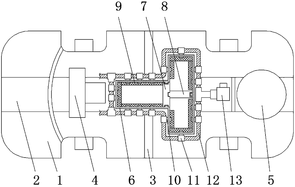
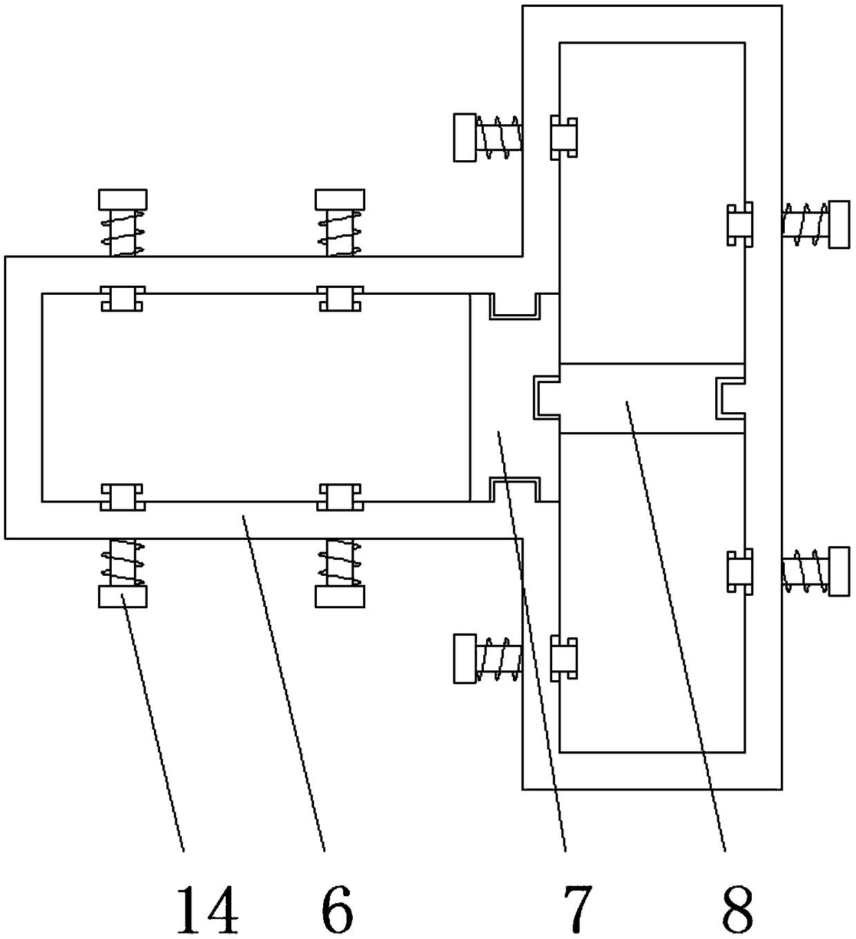
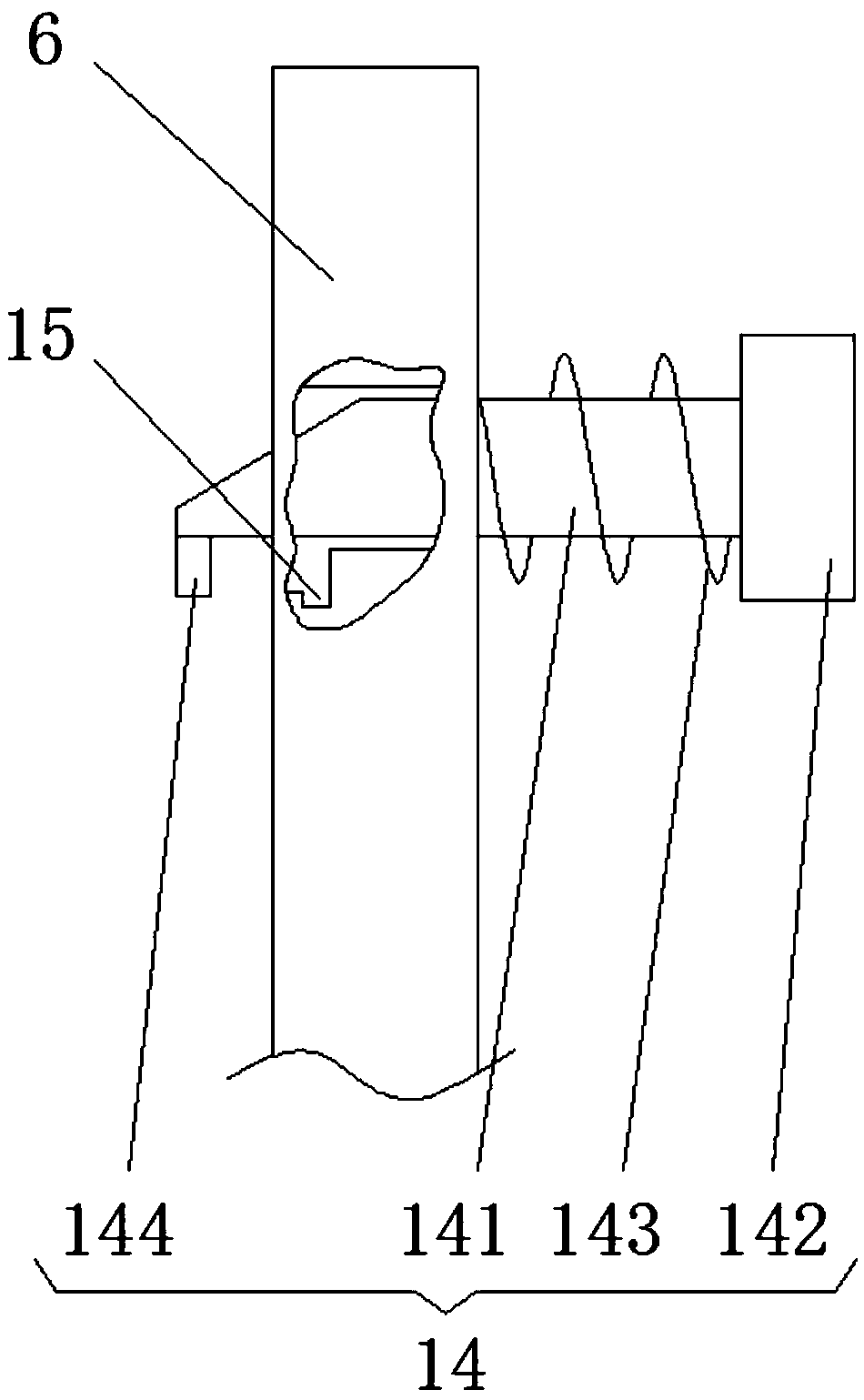
[0028] see Figure 1-4, a snap-on battery pack arrangement structure for a new energy vehicle, comprising a body floor 1, a body side member 2 and a body cross member 3 are respectively fixedly installed on the transverse and longitudinal central axes of the front side of the body body 1, and the front side of the body side member 2 and A central control area 4 is located on the vertical plane where the front wheels are located, and a gearbox is provided on on...


PUM


Abstract

The invention relates to the technical field of new energy vehicles, and discloses a clasp-type battery pack arrangement structure of a new energy vehicle, which comprises a body bottom plate, a bodylongitudinal beam and a body cross beam are fixedly installed on the transverse and longitudinal central axes of the front side of the body bottom plate respectively, a central control zone is arranged on the front side of the body longitudinal beam and on the vertical plane where the front wheels are located, and a transmission box is arranged on one side of the central control zone. Buckle-typebattery pack arrangement structure of that new energy vehicle, By setting the battery pack mounting box, and adopts T-shaped symmetrical distribution mode, so that the battery pack is reasonably arranged in the battery pack mounting box, At that same time, a heat transfer pad is arrange in the battery pack mounting box, so that the stability of the battery pack fix in the battery pack mounting boxis ensured, and the vibration generated in the vehicle travel process can be partially eliminated by the heat transfer pad, thereby providing a stable working environment for the battery pack and facilitating unified management of the battery pack.

Description

technical field [0001] The invention relates to the technical field of new energy vehicles, in particular to an arrangement structure of snap-on battery packs for new energy vehicles. Background technique [0002] The battery pack of a new energy electric vehicle centrally protects and manages multiple battery packs, prevents the battery pack from entering water, and at the same time regulates the battery temperature to prevent the battery pack from being damaged by impact or even ignited and exploded. It is the core component of an electric vehicle. At present, there are generally two types of battery pack layout methods, namely centralized and distributed. The centralized layout structure is mainly to place the battery pack at the center beam of the car, or the front compartment of the car body, or under the trunk of the car body. , the centralized layout is conducive to the unified replacement, maintenance and management of batteries, and the routing of cables is convenie...

Claims


Application Information

Patent Timeline
Patent Type & Authority Applications(China)
IPC IPC(8): B60K1/04H01M2/10H01M10/613H01M10/625H01M10/6554H01M10/6556H01M10/6563
CPCB60K1/04H01M10/613H01M10/625H01M10/6554H01M10/6556H01M10/6563H01M50/20Y02E60/10
Inventor 淡建林
Owner 重庆得润汽车电子研究院有限公司
Why Eureka
Try Eureka