An unmanned aerial photographer which freely adjusts the angle of shooting

A technology of shooting angle and aerial camera, which is applied in the field of unmanned aerial camera, can solve problems such as disconnection and line winding, and achieve the effect of wide shooting range, quick adjustment of angle, and fast speed

Inactive Publication Date: 2018-12-11
ZHENGZHOU JIZHI TECH CO LTD
View PDF0 Cites 3 Cited by
  • Summary
  • Abstract
  • Description
  • Claims
  • Application Information

AI Technical Summary

Problems solved by technology

[0005] The purpose of the present invention is to solve the problem that the existing aerial camera uses a servo motor to adjust the shooting angle. If the servo motor breaks down, it is easy to cause the circuit to be wound or even disconnected. A free adjustment of the shooting angle is provided. unmanned aerial camera

Method used


Image

  • An unmanned aerial photographer which freely adjusts the angle of shooting
  • An unmanned aerial photographer which freely adjusts the angle of shooting
  • An unmanned aerial photographer which freely adjusts the angle of shooting

Examples


Embodiment 1

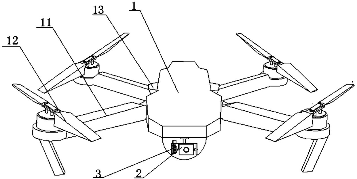
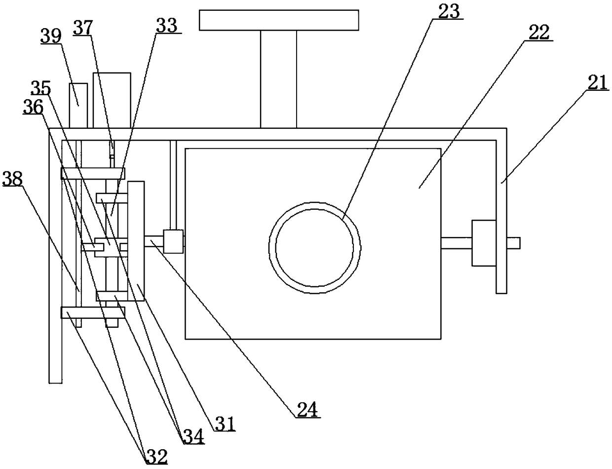
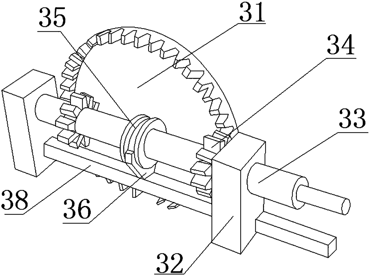
[0031] An unmanned aerial camera capable of freely adjusting shooting angles, comprising an aerial camera body 1 and a camera assembly 2, the camera assembly 2 comprising a mounting frame 21, a camera housing 22 and a camera 23 arranged in the camera housing, the camera housing Both sides of the body 22 are provided with rotating shafts 24, wherein the rotating shaft 24 on one side is connected to the mounting frame 21, and the rotating shaft 24 on the other side is connected to the mounting frame 21 through the drive assembly 3, and the mounting frame 21 is connected to the bottom of the aerial camera body 1, so The drive assembly 3 includes a face gear 31 fixedly connected to the end of the rotating shaft 11, two sets of fixed blocks 32 are arranged on the mounting bracket outside the face gear 31, and a linear rotary bearing is arranged inside the fixed block 32. The two sets of fixed blocks 32 The axes of the linear rotary bearings are the same, and the linear rotary bearin...

Embodiment 2

[0033] On the basis of Embodiment 1, the reciprocating assembly includes a linear bearing arranged below the linear rotary bearing in the fixed block 32. The axes of the linear bearings of the two sets of fixed blocks 32 are the same, and the inner sleeve of the linear bearing is provided with an adjustment A rod 38 , one end of the regulating rod 38 is connected with a cylinder 39 that drives the regulating rod 38 to reciprocate along the axial direction of the linear bearing.

Embodiment 3

[0035] On the basis of Embodiment 1 or 2, a controller is also included, and both the motor and the cylinder 39 are electrically connected to the controller.


PUM


Abstract

The invention discloses an unmanned aerial photographer which freely adjusts photographing angle. The unmanned aerial photographer includes an aerial photographer body and a camera assembly; the camera assembly includes a mounting bracket, a camera house and a camera head; rotating shaft is arranged on both sides of the camera housing, a shaft is connected to that mounting bracket through a driveassembly, the mounting bracket is connected to the bottom of the aerial photographer body; a drive assembly includes an end face gear, two set of fixing block are arranged at that outside of the end face gear, a linear rotation bear is arranged in that fix block, a driving rod is arranged in the linear rotation bearing, one end of the driving rod is connected with the output shaft of the motor, agear set is arranged on the driving rod between the two groups of fixed blocks, a bearing sleeve is arranged on the driving rod between the two groups of fixed blocks, and the lower end of the bearingsleeve is connected with a reciprocating component through a connecting rod. The present invention solves the problem that if the servo motor of the existing aerial photographer fails, it is easy tolead to wire winding or even wire breakage, and has the advantages of wide shooting range, rapid adjustment angle and high equipment stability.

Description

technical field [0001] The invention relates to the field of unmanned aerial photography devices, in particular to an unmanned aerial photography device capable of freely adjusting shooting angles. Background technique [0002] Aerial photography, also known as aerial photography or aerial photography, refers to taking pictures of the earth's landforms from the air to obtain a top view. This picture is an aerial photo. At present, most of the aerial photography is to install the camera on the aerial photography device, and to shoot the desired image by controlling the flight path of the aerial photography device. [0003] At present, aerial photography devices have been well utilized in many places, such as: water conservancy and hydrological observation, TV program recording, etc., and even some important celebrations have also appeared in aerial photography devices. At present, the camera of the aerial camera generally has two forms. One is to use the automatic imaging eq...

Claims


Application Information

Patent Timeline
Patent Type & Authority Applications(China)
IPC IPC(8): B64C27/08B64D47/08G03B17/56G03B30/00
CPCG03B17/561B64C27/08B64D47/08B64U10/10B64U2101/30
Inventor 孔汉
Owner ZHENGZHOU JIZHI TECH CO LTD
Why Eureka
Try Eureka