
Novel fingerprint lock

A fingerprint lock, a new type of technology, applied in the field of security protection, can solve the problems of poor security protection capability of fingerprint locks, theft and use by criminals, and physical pain of users, so as to reduce the use of fingerprints by theft, avoid bacterial legacy and infection, The effect of reducing impact damage

Inactive Publication Date: 2018-12-11
郴州多特科技发展有限公司
View PDF9 Cites 4 Cited by
  • Summary
  • Abstract
  • Description
  • Claims
  • Application Information

AI Technical Summary

Problems solved by technology

[0003] The present invention provides a new type of fingerprint lock, which can effectively solve the problem in the above background technology that the current fingerprint locks on the market have poor security protection capabilities. When the user pushes the door through the handle, the imprint of the fingerprint remains on the surface of the handle, which is easy to be stolen by criminals. After the use, it will cause economic loss to the user. When the finger is pressed on the surface of the fingerprint input device, the fingerprint is also left behind. It is also easy to be stolen and used by criminals. When used at night, the existing fingerprint lock is not convenient for the user to align the fingerprint. It is easy to cause fingers to poke the lock body, causing physical pain to the user, which is not conducive to the user to open the door quickly. The existing fingerprint lock does not have a device to protect the front cover, which may easily lead to blockage of the lock hole, password keyboard and fingerprints. If the logger is damaged, the fingerprint lock cannot be used normally, which will affect the life of the user

Method used


Image

  • Novel fingerprint lock
  • Novel fingerprint lock
  • Novel fingerprint lock

Examples


Embodiment

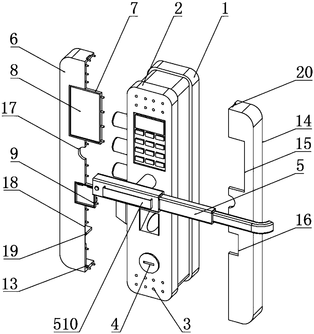
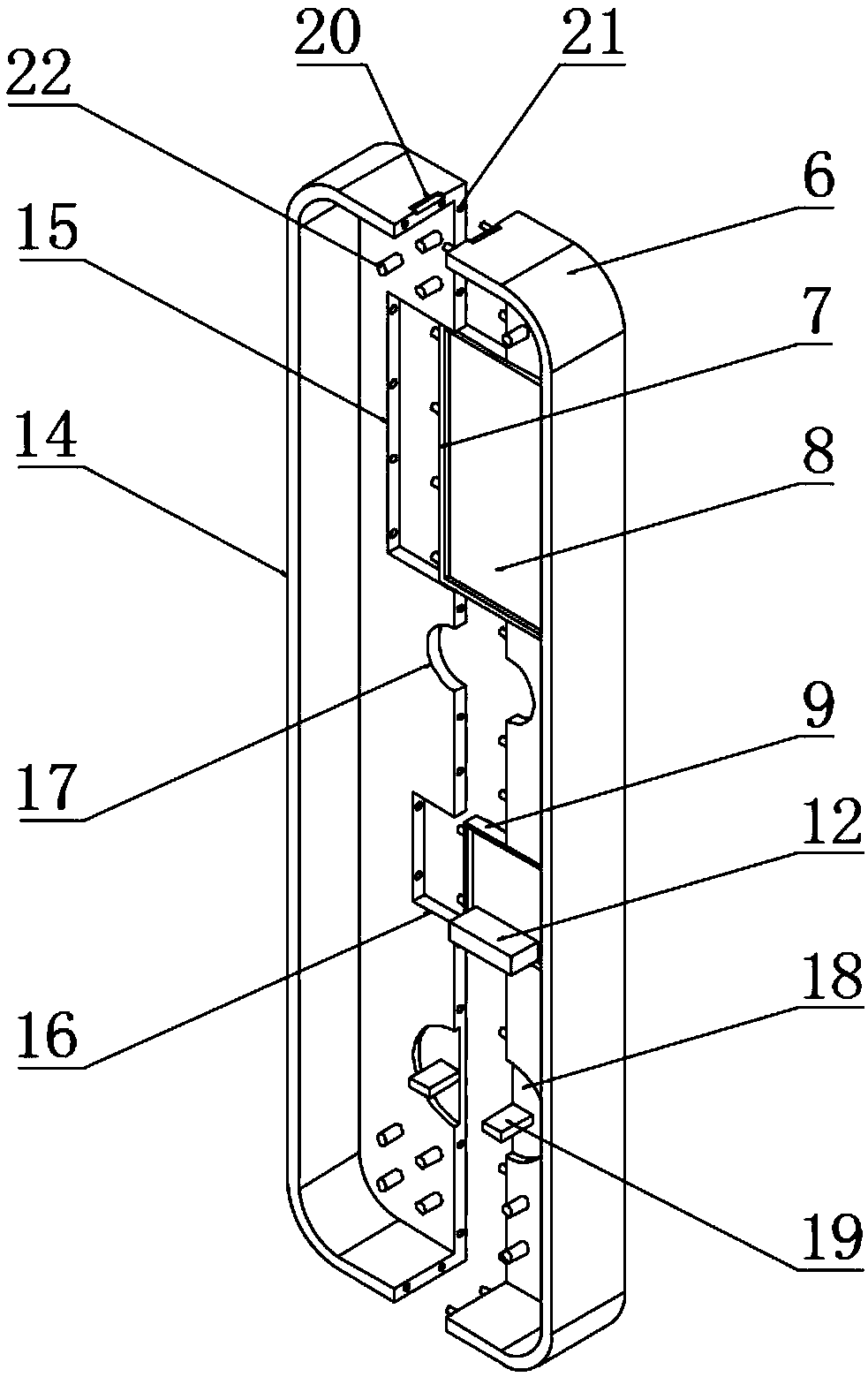
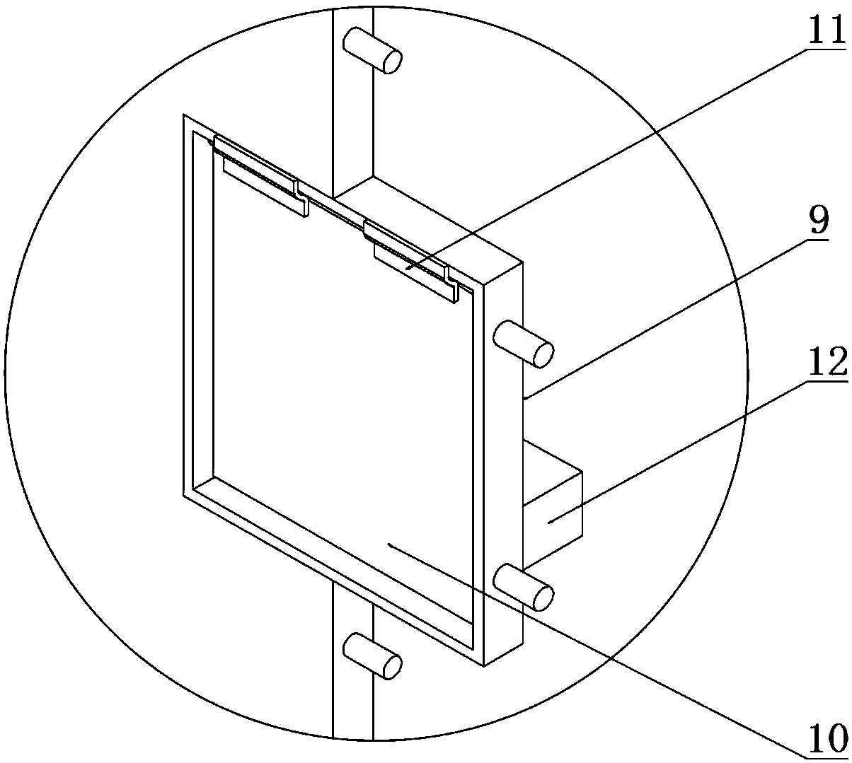
[0027] Example: such as Figure 1-5 As shown, the present invention provides a technical solution, a novel fingerprint lock, including a fingerprint lock body 1, a front cover 2 is installed on the front side of the fingerprint lock body 1, and a fixed cover is evenly opened on the top and bottom of the outer surface of the front cover 2. Hole 3, emergency lock head 4 is installed below front cover plate 2, and push-pull mechanism 5 is installed in the middle of front cover plate 2, and push-pull mechanism 5 comprises rotating shaft 501, first sleeve pipe 502, adjustment spring 503, second sleeve pipe 504, Push rod 505, scraper 506, button battery 507, switch 508, LED light bar 509 and dimming assembly 510, the first sleeve 502 is installed on one end of the rotating shaft 501, the first sleeve 502 is installed with the first sleeve 502 through the adjustment spring 503 Two bushings 504, the inside of the second bushing 504 is equipped with a push rod 505 through the adjustmen...


PUM


Abstract

The invention discloses a novel fingerprint lock, which comprises a fingerprint lock body,a front cover plate is arranged on the front side of the fingerprint body, a first protective shell is arranged on one side of the front cover plate, a second protective shell is arranged on the other side of the front cover plate, corresponding to the first protection shell, a push-pull mechanism is arrangedat the middle part of the front cover plate, according to the invention, the structure is scientific and reasonable, the use is convenient, the first protective shell and the second protection shellcan effectively protect the fingerprint lock body and reduce the damage of the front cover plate,an emergency lock head is hidden, so that a lawbreaker is prevented from unlocking by using the emergency lock head; the surface of a fingerprint input device is cleaned by the cleaning block at the bottom of the protective plate, residual fingerprint marks on the surface of the fingerprint input device are avoided, the situation that the fingerprint is stolen and utilized by the lawbreaker is avoided, the surface cleaning of the fingerprint input device is ensured, and the fingerprint is input conveniently and more accurately; the surfaces of a second sleeve and push rod can be cleaned by a doctor blade so as to avoid bacterial carryover and infection caused by different users when the lock isused.

Description

technical field [0001] The invention relates to the technical field of security protection, in particular to a novel fingerprint lock. Background technique [0002] Fingerprint lock is an intelligent lock, which is a combination of computer information technology, electronic technology, mechanical technology and modern hardware technology. The characteristics of fingerprints become the most important evidence for identification and are widely used in public security criminal investigation and judicial fields. The uneven lines on the skin on the front of the terminal are different in patterns, breakpoints and intersections. It has been medically proven that these lines are different for each finger, and these lines are unique. The fingerprint lock collects the fingerprints of the residents of the house for storage, compares the fingerprints entered when opening the door, and performs the door opening operation under the processing of the smart chip, so as to achieve the funct...

Claims


Application Information

Patent Timeline
Patent Type & Authority Applications(China)
IPC IPC(8): E05B17/18E05B17/10E05B17/00E05B49/00G07C9/00
CPCE05B17/002E05B17/10E05B17/186E05B49/00G07C9/00563
Inventor 邓勇强
Owner 郴州多特科技发展有限公司
Learn More