Frictional-energy-consumption-longitudinal-beam-based hybrid spraying-steel frame overall avoidance changing initial-supporting structure and construction method thereof

A friction energy dissipation and longitudinal beam technology, which is applied in earth-moving drilling, wellbore lining, tunnel lining, etc., can solve the problems such as the inability to exert the function of the retractable steel frame and the loss of sliding function of the slidable joint. Enhance the co-deformation ability and the effect of convenient processing

Active Publication Date: 2018-12-11
KUNMING SURVEY DESIGN & RES INST OF CREEC
View PDF19 Cites 6 Cited by
  • Summary
  • Abstract
  • Description
  • Claims
  • Application Information

AI Technical Summary

Problems solved by technology

Therefore, during the application process, the joint structure cannot be co-deformed together with the shotcrete under the condition of large vertical and radial deformations. It often shows that the steel frame and the shotcrete are separated, and even the shotcrete limits the shrinkable steel structure. frame movement, or the joints are sprayed with concrete cau...

Method used


Image

  • Frictional-energy-consumption-longitudinal-beam-based hybrid spraying-steel frame overall avoidance changing initial-supporting structure and construction method thereof
  • Frictional-energy-consumption-longitudinal-beam-based hybrid spraying-steel frame overall avoidance changing initial-supporting structure and construction method thereof
  • Frictional-energy-consumption-longitudinal-beam-based hybrid spraying-steel frame overall avoidance changing initial-supporting structure and construction method thereof

Examples


Embodiment Construction

[0052] The preferred embodiments of the present invention will be described in detail below in conjunction with the accompanying drawings, so that the advantages and features of the present invention can be more easily understood by those skilled in the art, so as to define the protection scope of the present invention more clearly.

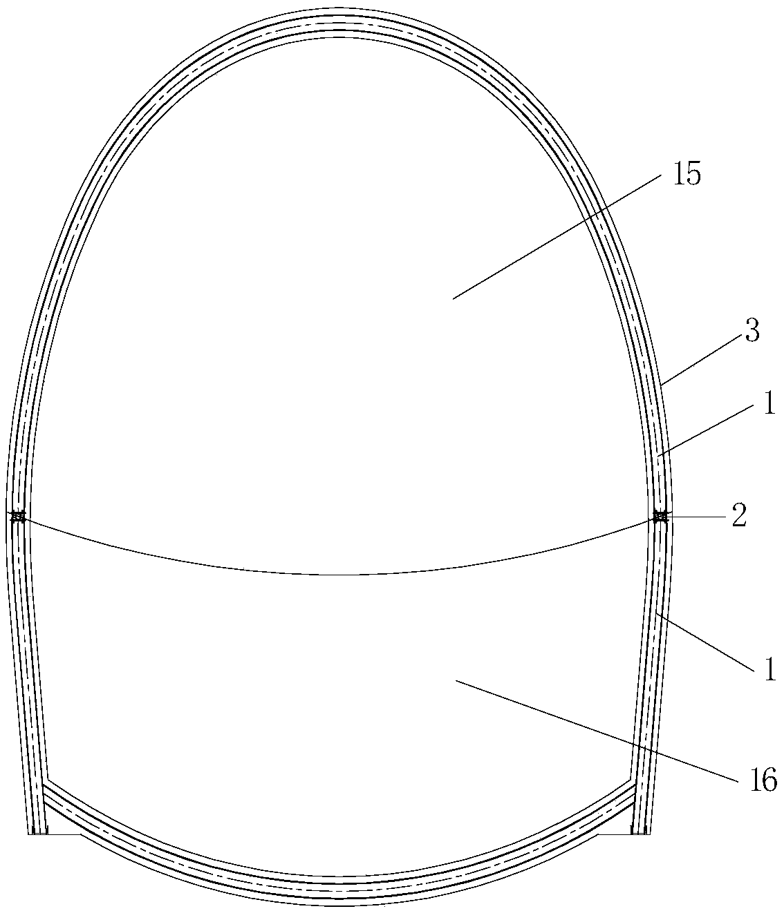
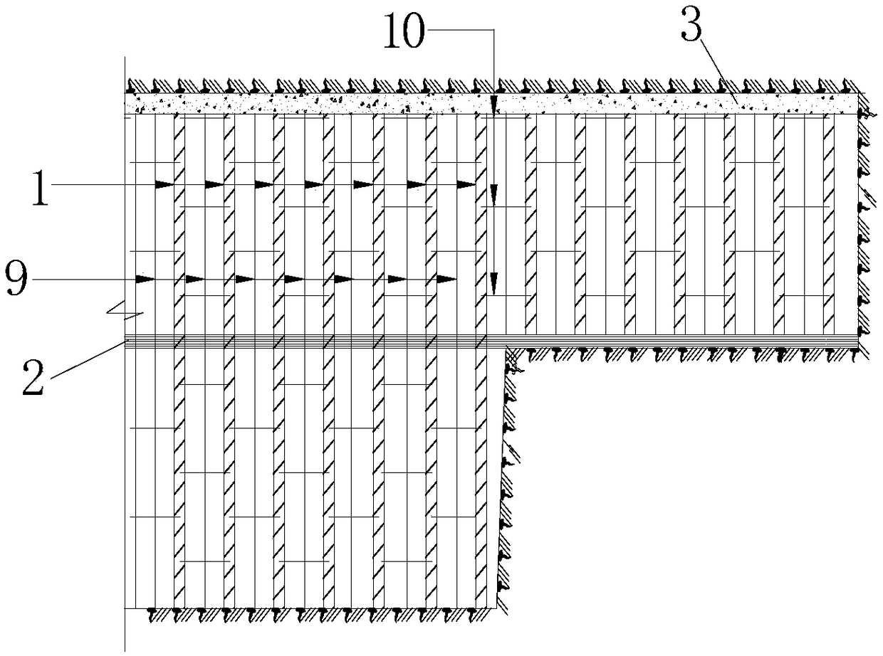
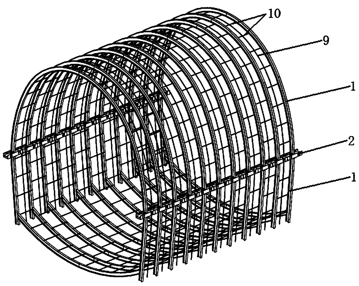
[0053] like Figure 1~9 As shown, the sprayed-concrete-steel frame structure based on frictional energy-dissipating longitudinal beams includes steel frame 1, frictional energy-dissipating longitudinal beams 2, and shotcrete 3. The steel frame 1 is formed by cold-bending section steel; the frictional energy-dissipating longitudinal beam is composed of an upper bearing part 4 and a lower bearing part 5 made of channel steel, bolt holes 6 are set on the wing plate of the upper bearing part 4, and the wings of the lower bearing part 5 A strip chute 7 is arranged on the board, and the upper bearing part 4 and the lower bearing part 5 are connected by...


PUM


Abstract

The invention discloses a frictional-energy-consumption-longitudinal-beam-based hybrid spraying-steel frame overall avoidance changing initial-supporting structure and a construction method thereof. The structure comprises a steel frame, a frictional energy consumption longitudinal beam, a sprayed concrete, reinforcing meshes, longitudinal threaded steel bars, and circumferential threaded steel bars. The steel frame is formed by bold bending of profile steels. The frictional energy consumption longitudinal beam mainly includes an upper support member and a lower support member that are made ofchannel steels; and energy is consumed by the friction effect between flanges of the upper support member and the lower support member. And the longitudinal threaded steel bars and the circumferential threaded steel bars are added in the sprayed concrete between two steel frame units. While coordinated deformation of the initial support of the tunnel and the surrounding rock, the frictional energy consumption longitudinal beam enables the initial support to have the certain pressing-resistant and shearing-resistant performances; with the longitudinal steel bars and circumferential steel barsand longitudinal arrangement of the frictional energy consumption longitudinal beam, the joint deformation capability of the tunnel steel frame and the initial supporting structure formed by the sprayed concrete between the steel frames is strengthened, so that the structure damage caused by deformation incompatibility of the steel frame and the sprayed concrete is avoided and thus a coupling effect of the harness with softness is realized.

Description

technical field [0001] The invention belongs to the technical field of tunnel engineering support, and in particular relates to a spray-mixed-steel frame integral change initial support structure and construction method based on frictional energy-dissipating longitudinal beams, which is an overall change of the stress mode of the existing tunnel initial support structure , which is suitable for the control of large deformation disasters in the initial support of tunnel engineering. Background technique [0002] In order to solve the problem of unbalanced and insufficient development in the eastern and western regions of our country, the construction of infrastructure such as transportation and water conservancy is gradually inclined to the west. The construction of industrial tunnels is in a period of rapid development. Because the western region is located in the collision zone of the continental plate, the lithology of the surrounding rock is variable, the rock mass is ...

Claims


Application Information

Patent Timeline
IPC IPC(8): E21D11/18E21D11/28E21D11/10
CPCE21D11/10E21D11/18E21D11/28
Inventor 郭永发田鲁鲁殷洪波杨进京丁文云杜建军徐涛张海波陶伟明杨翔罗云飞罗胜利刘正初赵海燕李贵民
Owner KUNMING SURVEY DESIGN & RES INST OF CREEC
Why Eureka
Try Eureka